Check valve for charge tank

a technology of charge tank and check valve, which is applied in the direction of functional valve types, mechanical devices, contact material materials, etc., can solve the problems of high voltage power cable insulation degradation and system pressure fluctuation, and achieve the effect of preventing the energizing of fluid reservoirs

Active Publication Date: 2010-04-27
NOVINIUM LLC
View PDF26 Cites 12 Cited by
  • Summary
  • Abstract
  • Description
  • Claims
  • Application Information

AI Technical Summary

Benefits of technology

[0009]A system for preventing energizing a fluid reservoir is also provided. In one embodiment, the system includes a line from the fluid reservoir leading to an energized power cable. The system also includes a back-flow prevention device installed in any part of the line or within the fluid reservoir, wherein the back-flow prevention device may prevent the flow of fluid contaminated with conductive materials that may energize the fluid reservoir.

Problems solved by technology

The insulation of high voltage power cables will degrade after a period of time.
However, as the cable fills and the fluid system begins to stabilize, temperature changes that occur inside the cable or outside in the environment around the feed tank can cause the pressure of the system to fluctuate.

Method used


Image

  • Check valve for charge tank
  • Check valve for charge tank
  • Check valve for charge tank

Examples


Embodiment Construction

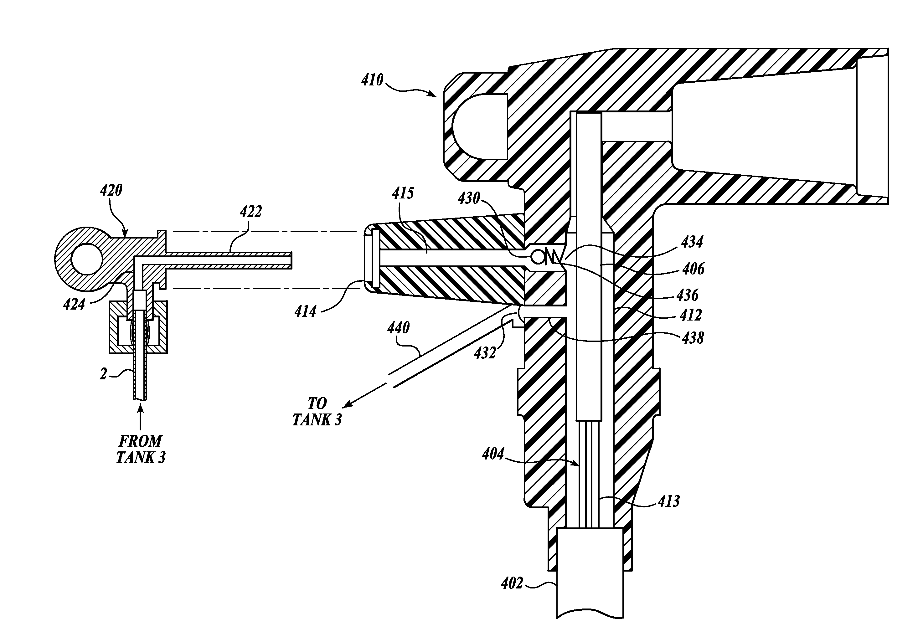
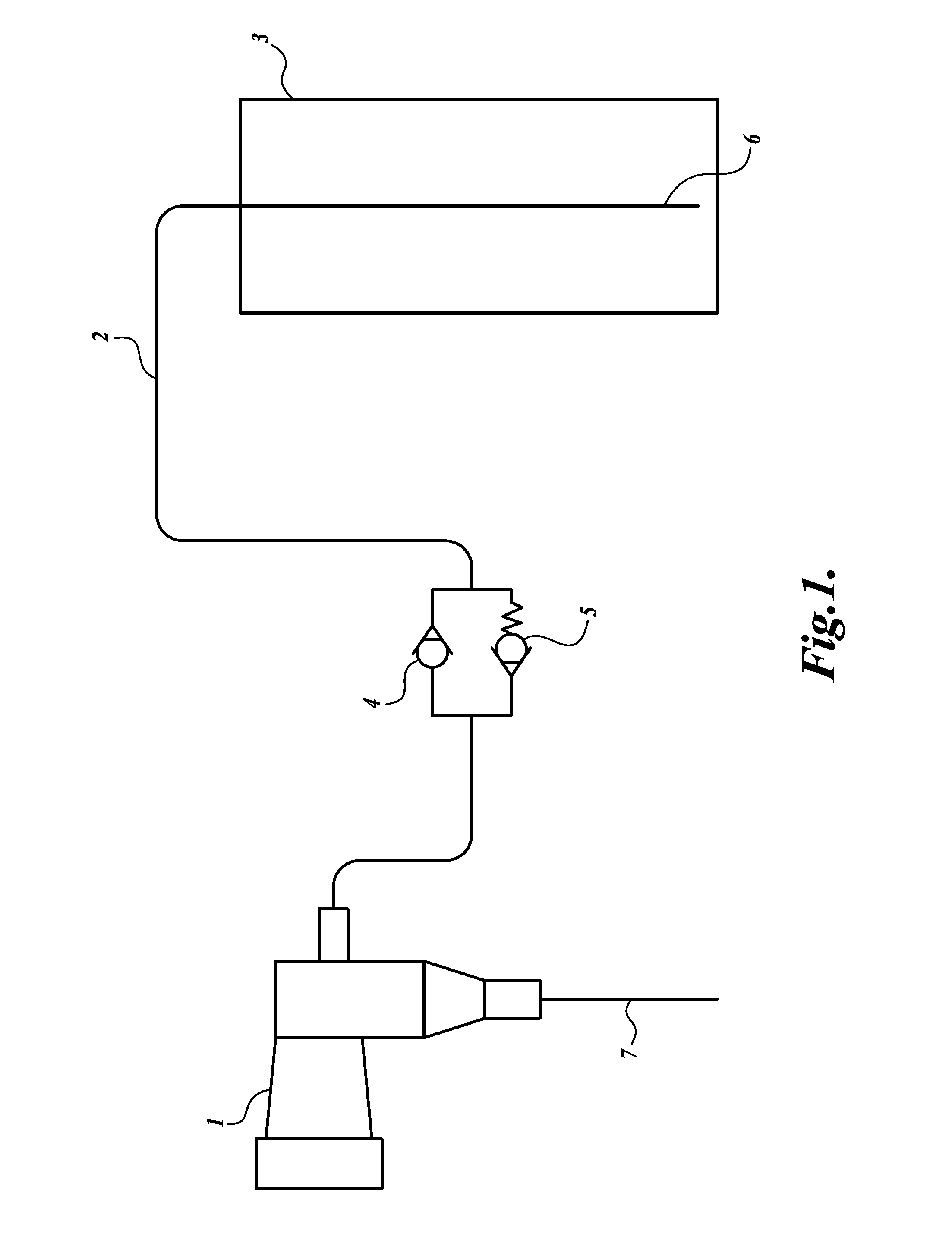
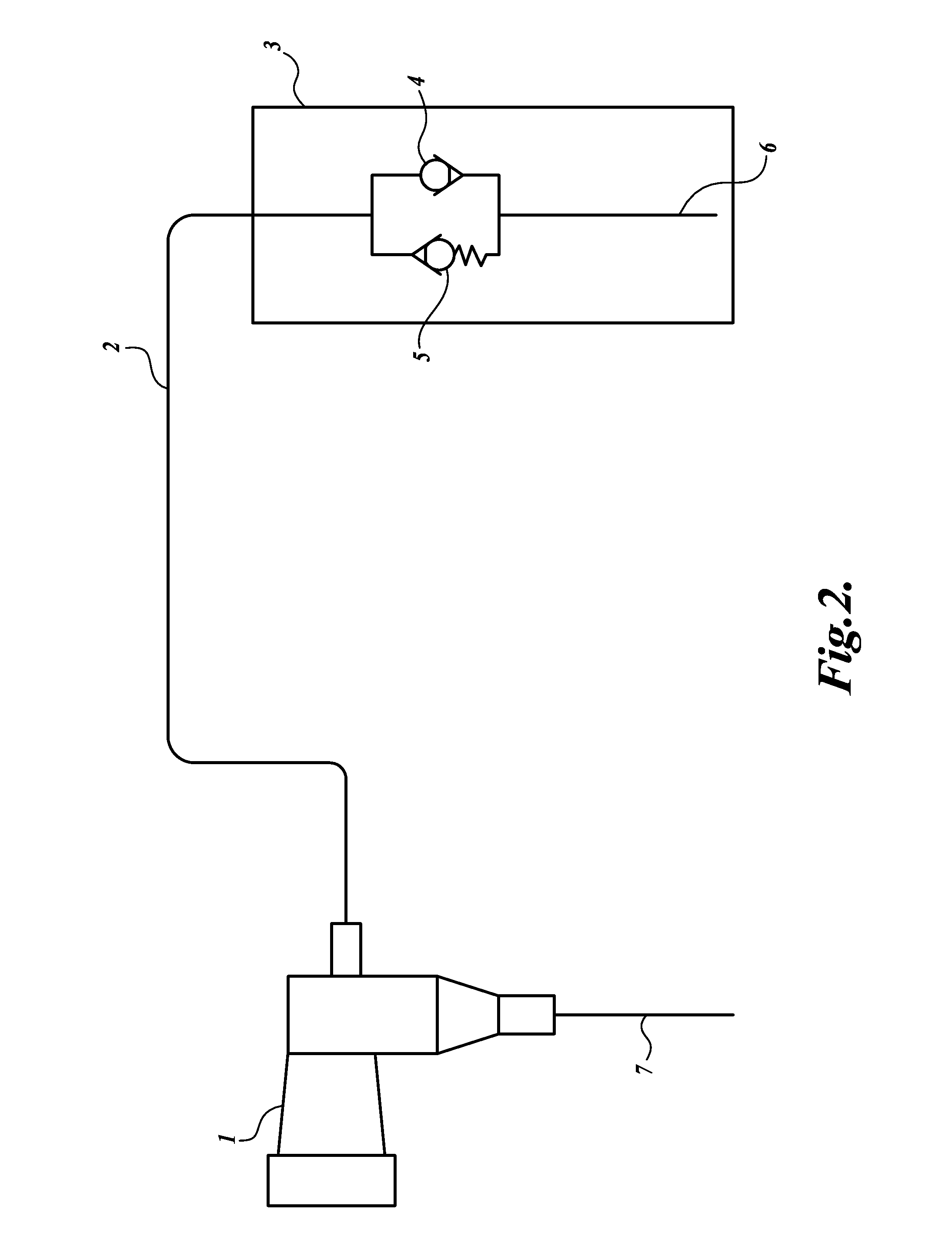
[0016]Referring to FIG. 1, a remediation fluid delivery system for remediating power cable insulation is schematically illustrated. The system includes a remediation fluid reservoir, such as feed tank 3, a fluid line 2 leading from the tank 3 to an injection termination 1, wherein the injection termination 1 is attached to power cable 7.

[0017]Remediation fluid is stored in the fluid feed tank 3 and can be supplied to the injection termination 1 (such as an injection elbow or other separable-type connector) via the fluid line 2. Fluid is drawn from the fluid feed tank 3 at the fluid inlet 6 of the fluid line 2. Fluid may flow by gravity from the tank 3 to the injection termination 1. A back-flow prevention device 4 is installed in the line 2 that allows the flow of fluid from the tank 3 to the injection termination 1, but prevents the flow of fluid from the injection termination 1 to the tank 3.

[0018]The system may also include a pressure relief device 5, installed in the line 2, tha...


PUM


Abstract

A method and apparatus are described to prevent the unwanted energizing of equipment not normally intended to be energized when delivering a fluid to an energized power cable. The method and apparatus relate to the installation of a fluid back-flow prevention device in the line or equipment carrying a fluid to the cable, and also providing a pressure relief device that may relieve excess pressure to prevent damaging equipment.

Description

CROSS-REFERENCE TO RELATED APPLICATION[0001]This application claims the benefit of U.S. Provisional Application No. 60 / 607,339, filed on Sep. 3, 2004, the disclosure of which is hereby expressly incorporated by reference.FIELD OF THE INVENTION[0002]The described embodiments relate to a process for power cables, and more particularly to a check value for a charge tank.BACKGROUND OF THE INVENTION[0003]The insulation of high voltage power cables will degrade after a period of time. One remediation process for the insulation of medium and high voltage power cables requires the injection of a remediation fluid into the free spaces of a cable. In many instances, the injection process takes place while the cables are energized. When the remediation process is performed on energized cables, special injection terminations (injection “elbows”) may be used. Injection terminations are similar to industry standard cable terminations except that they have a special access port designed to allow f...

Claims


Application Information

Patent Timeline
Patent Type & Authority Patents(United States)
IPC IPC(8): H01R4/60H01R4/64
CPCH02G15/26F16K17/19
Inventor STAGI, WILLIAM R.STEELE, JAMES
Owner NOVINIUM LLC
Why Eureka
Try Eureka