Device and a method for cleaning of a gas

a technology for cleaning devices and gas, applied in the direction of electric supply techniques, centrifuges, separation processes, etc., can solve the problems of insufficient kinetic energy in all applications, more difficult to provide an efficient and complete etc., and achieve efficient separation of particulate impurities and substantial separation

Active Publication Date: 2010-04-27
ALFA LAVAL CORP AB
View PDF18 Cites 13 Cited by
  • Summary
  • Abstract
  • Description
  • Claims
  • Application Information

AI Technical Summary

Benefits of technology

[0007]The object of the present invention is to provide a device for an efficient separation of particulate impurities from a gas. More specifically, it is aimed at an efficient separation of substantially all particulate impurities of different sizes and different kinds.
[0010]According to an embodiment of the invention the electrostatic filter includes a first pole element, a second pole element, and a voltage unit, which provides an electric potential difference between the first pole element and the second pole element in such a way that the first pole element charges the particulate impurities in the gas with an electric potential in relation to the second pole element and that the second pole element attracts the charged particulate impurities for separating them from the gas. By such an additional separator, substantially the whole rest amount may in an easy and efficient manner be removed from the gas.

Problems solved by technology

A sufficient kinetic energy is however not available in all applications, which, for instance in an engine application, means that the crankcase gas has to be given kinetic energy by means of a pump or there like.
These requirements, which are especially expressed for motor vehicles, makes it more difficult to provide an efficient and complete separation of particulate impurities.

Method used


Image

  • Device and a method for cleaning of a gas
  • Device and a method for cleaning of a gas
  • Device and a method for cleaning of a gas

Examples


Embodiment Construction

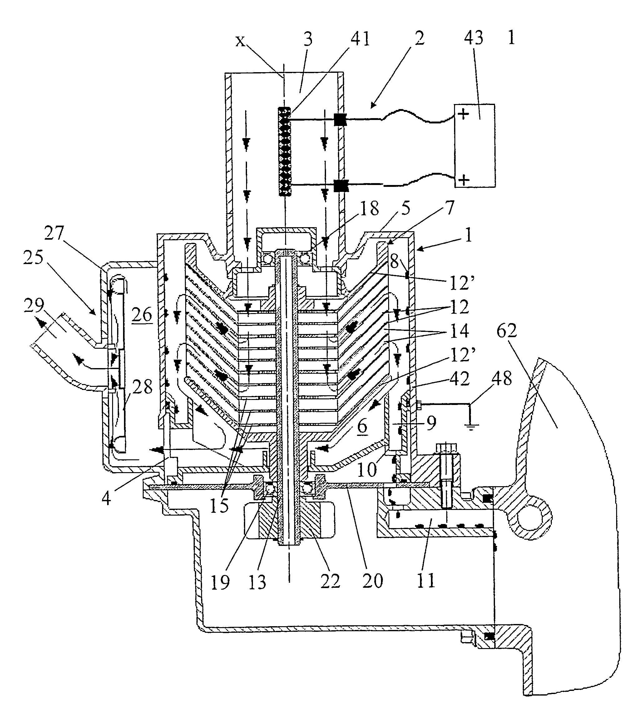
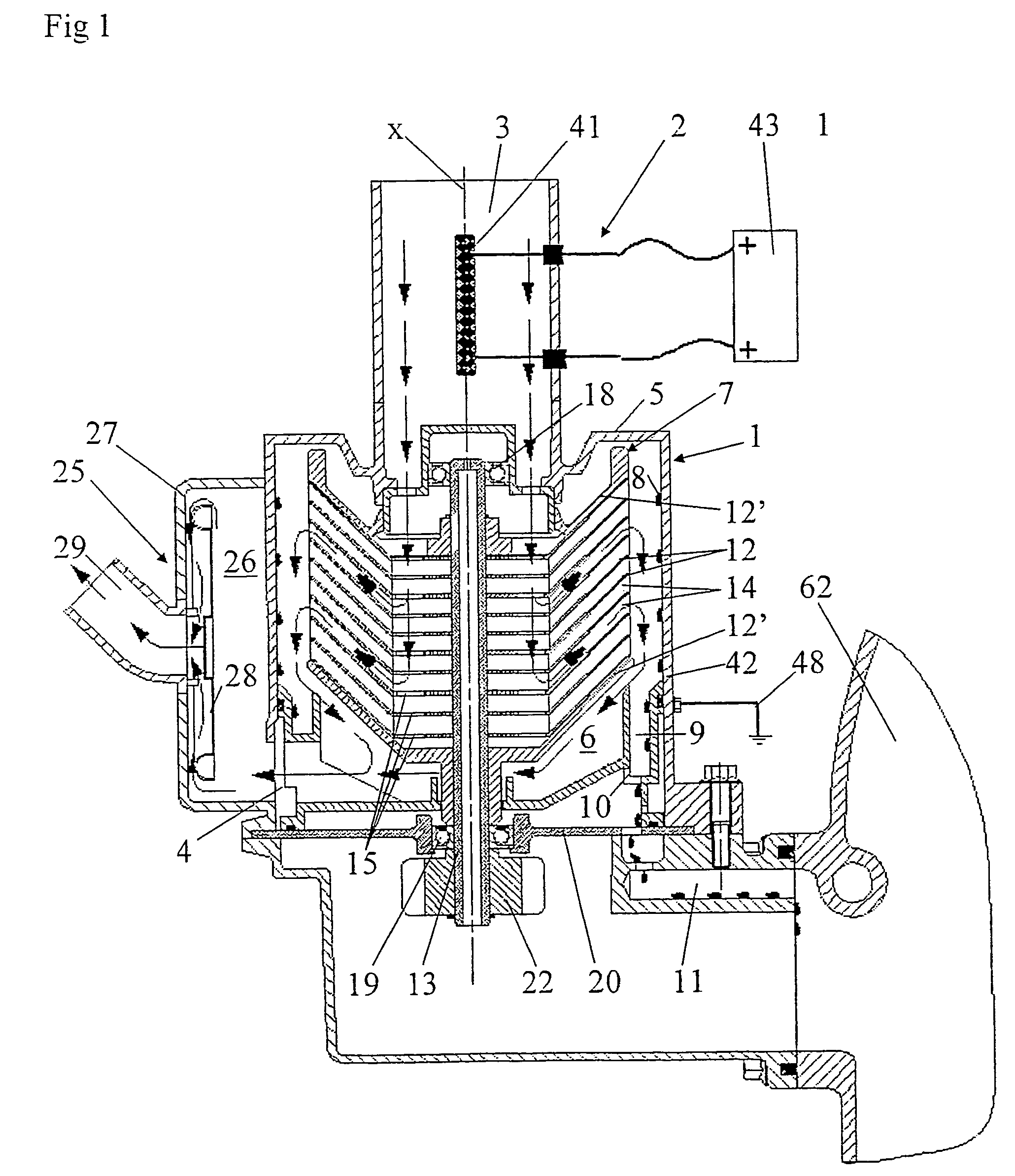
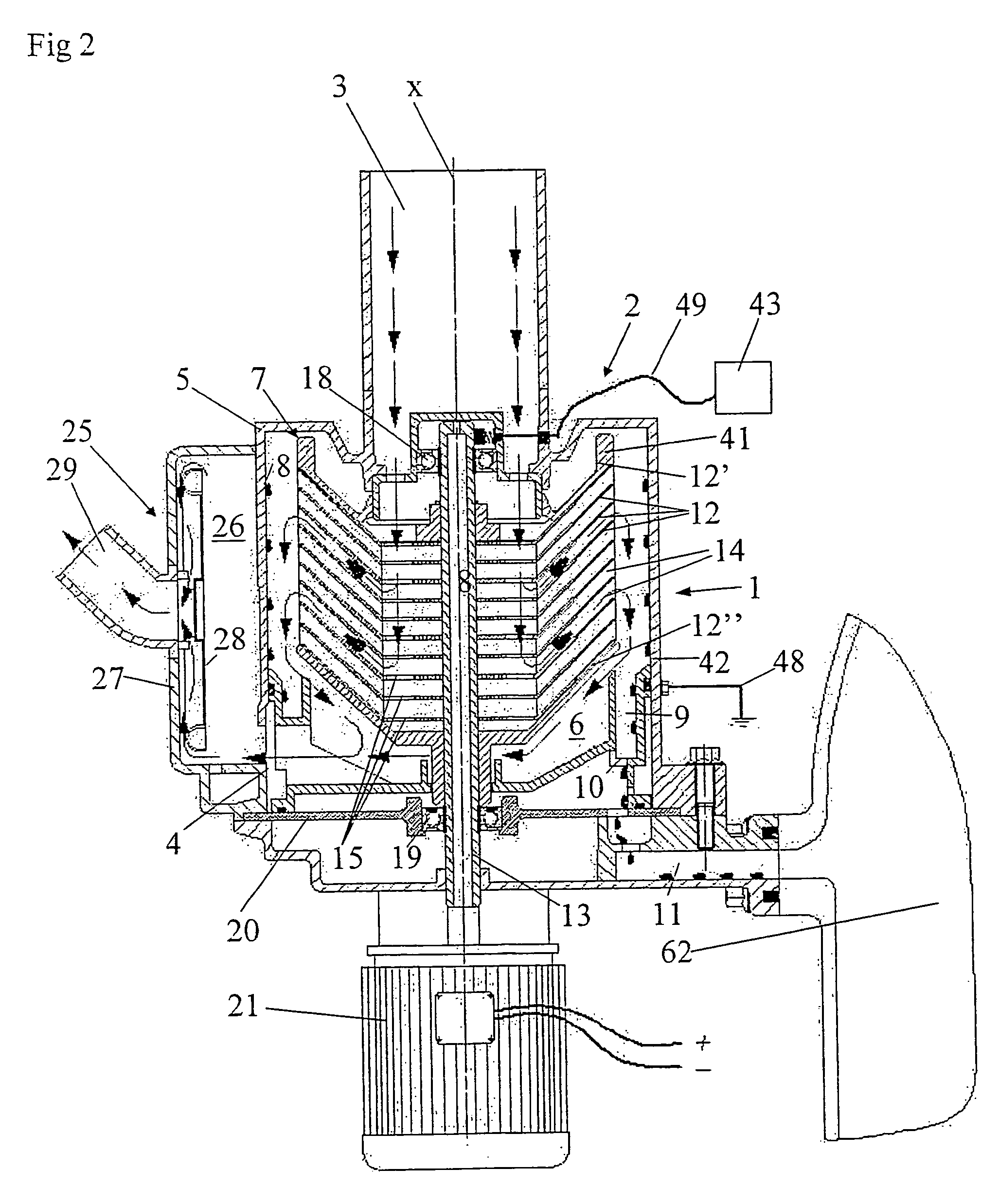
[0033]FIGS. 1-3 disclose various embodiments of a device for cleaning of a gas containing particulate impurities. The device includes a main separator 1 and an additional separator 2 in the form of an electrostatic filter to be described more closely below. The main separator 1 includes an inlet 3 for the gas to be cleaned and an outlet 4 for the gas. The device includes a stationary housing 5 which defines an inner chamber 6. The inlet 3 extends through the stationary housing 5 into the chamber 6. The outlet 4 extends from the chamber 4 through the stationary housing 5. The main separator 1 also includes a rotating member 7 which is provided in the chamber 6 between the inlet 3 and the outlet 4. The rotating member 7 is rotatable about a rotary axis x and designed as an open centrifuge rotor adapted to bring the gas from the inlet 3 in rotation for the separation of a main amount of the particulate impurities from the gas by means of centrifugal forces. The stationary housing 5 has...


PUM

PropertyMeasurementUnit
particle sizeaaaaaaaaaa

Abstract

The invention refers to a device and a method for cleaning a gas containing particulate impurities. The device includes a main separator having an inlet for the gas, an outlet for the gas and a rotating member provided between the inlet and the outlet. The rotating member is adapted to bring the gas to rotate for separating by means of centrifugal forces a main amount of the particulate impurities from the gas, wherein a rest amount of the particulate impurities remains in the gas. The device also includes an additional separator adapted to separate substantially the whole rest amount. The additional separator includes an electrostatic filter.

Description

FIELD OF THE INVENTION[0001]The present invention refers generally to cleaning of a gas through separation of particulate impurities from the gas. More specifically it is directed to the separation of oil particles, in the form of droplets or a mist, and / or solid particles from the gas. In particular the invention refers to cleaning of gases from a crankcase in a combustion engine and cleaning of air in various applications within the machine tool industry, for instance the air around various kinds of machine tools. Such gases and such air contain particulate impurities of different sizes. The invention refers however also to other applications where a gas needs to be cleaned from particulate impurities of different kinds and different sizes.[0002]The present invention refers especially to a device for cleaning of a gas containing particulate impurities, wherein the device includes a main separator having an inlet for the gas, an outlet for the gas and a rotating member, which is ar...

Claims


Application Information

Patent Timeline
Patent Type & Authority Patents(United States)
IPC IPC(8): B03C3/011B01D45/14B01D46/50B03C3/01B03C3/15B04B5/10B04B5/12F01MF01M13/04
CPCB01D45/14B01D46/4245B01D46/50B01D50/002B03C3/011B03C3/15B04B5/12B04B5/10Y10S55/19B04B2005/125F01M2013/0422F01M2013/0466Y10S55/18B01D50/20F01M13/04B03C3/01
Inventor SZEPESSY, STEFAN
Owner ALFA LAVAL CORP AB
Why Eureka
Try Eureka