Traffic signal column

a technology of traffic signal and column, applied in the field of signal column, can solve the problems of contact fault, complicated manufacturing method, and inability to manufacture such conductors entirely assuming interconnection functions

Active Publication Date: 2010-04-27
SCHNEIDER ELECTRIC IND SAS
View PDF14 Cites 3 Cited by
  • Summary
  • Abstract
  • Description
  • Claims
  • Application Information

AI Technical Summary

Benefits of technology

[0020]According to another particular feature, the body of the stage has, at the opposite end from the base of the stage, a sup...

Problems solved by technology

The manufacture of such conductors entirely assuming the interconnection function is complicated.
However, this arrangement may result in contact faults because the connection quality is entirely assumed by the shape and elasticity of the conductors.
The disadvantage is that, if it is desired to give the various stag...

Method used


Image

  • Traffic signal column
  • Traffic signal column
  • Traffic signal column

Examples


Embodiment Construction

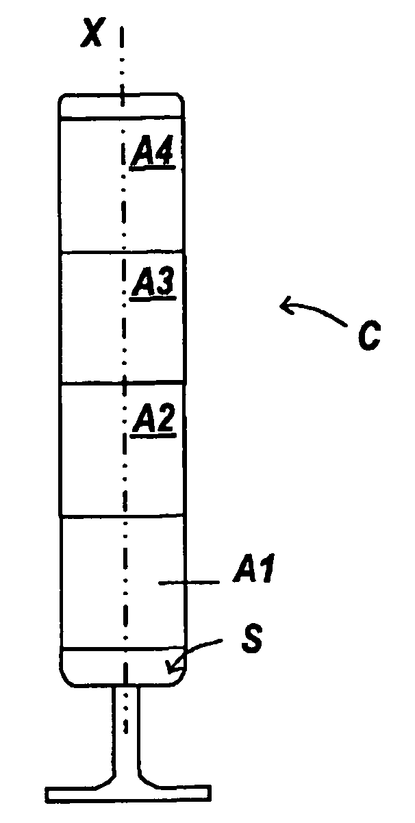
[0030]The signal column C illustrated in the figures comprises a number of stacked signaling stages or modules A. As can be seen from FIG. 1, the column C extends along a vertical axis X and has four stages A1-A4 fastened to one another, the lowermost stage A1 being fastened to a pedestal S that ensures passage for the electrical conductors, the uppermost stage A4 being, for example, capped by a cover. The column may of course have a different number of stages.

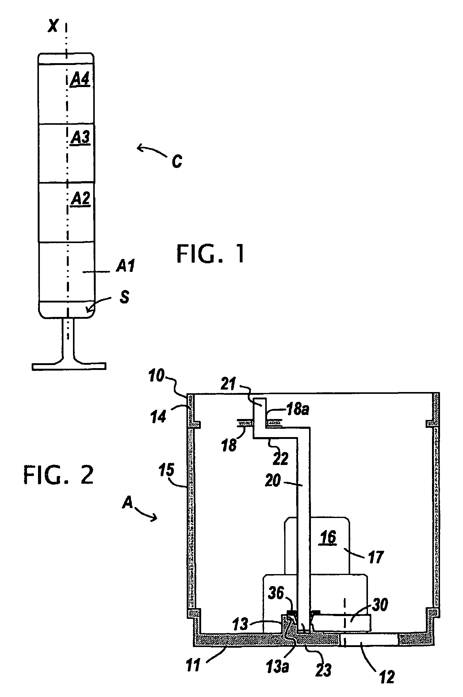
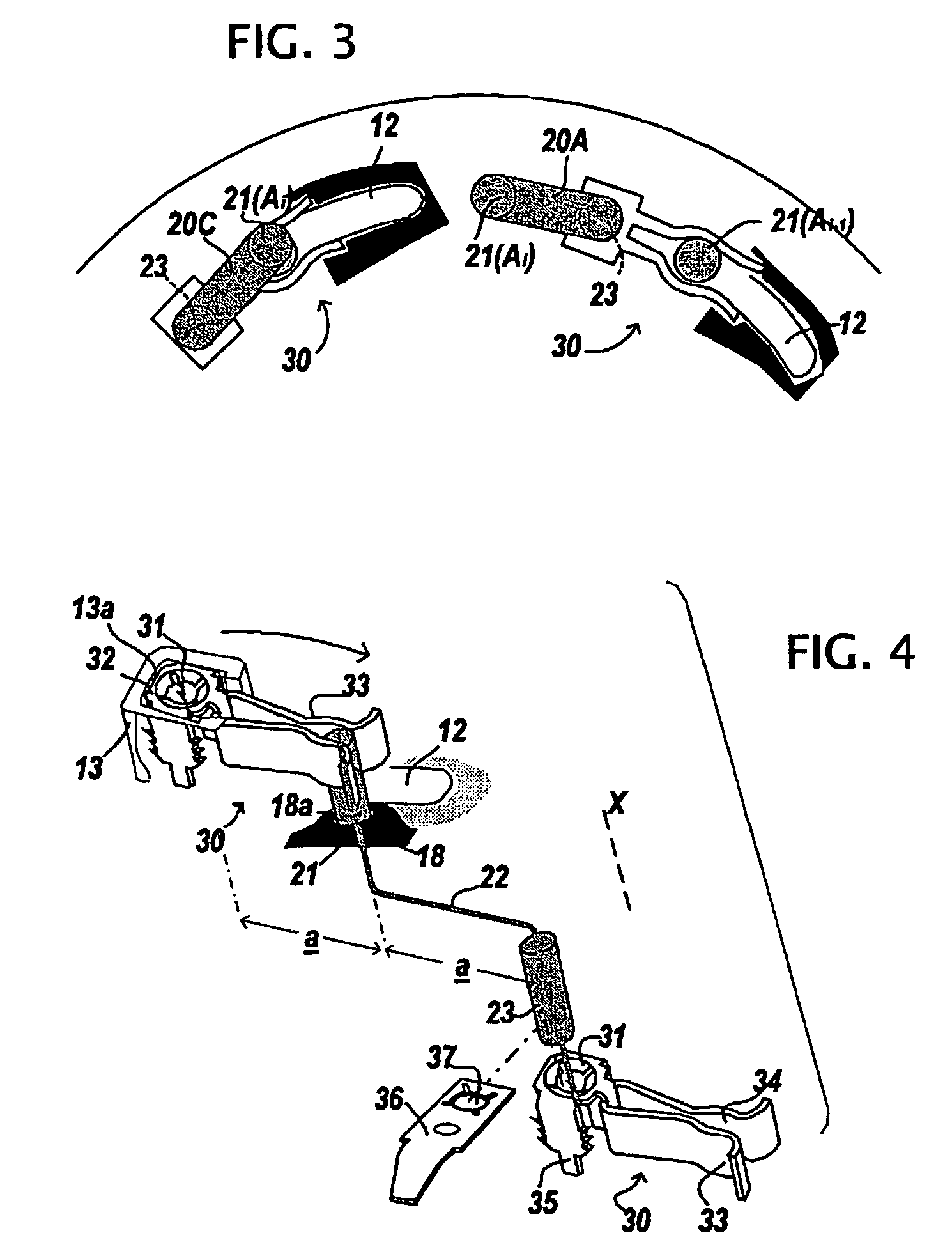
[0031]The body 10 of a stage Ai houses a number of conducting rods 20. For the sake of clarity, FIG. 2 shows a single rod of a stage Ai. The body 10, which is of cylindrical or prismatic shape with axis X, has a base 11 provided around its periphery (see FIGS. 3 and 5 to 8) with a number of curved passages 12 and with studs 13 adjacent to these passages and intended to receive connectors 30. At the opposite end from the base (that is to say towards the top in the figures), the body 10 has a support 14 such as a cap or a frame ...


PUM


Abstract

An optical traffic signal column including stacked levels fixed to one another by rotation. The base of each level includes, distributed along its periphery, oblong passages and fixed connectors. The conductors include rods each having two ends angularly offset from one another, and including a common conducting rod and a stage-specific conducting rod. The connector rods are identical and respectively fix the bottom of a conducting rod of the relevant level and the top of the respective conducting rod of an adjacent level, the angular offset between the two fixing points corresponding to that of ends of the conducting rods. The conducting rods are mutually arranged and mounted to effect, from one level to the next level, an essentially identical angular position of the common conducting rods and an angular offset of the stage-specific conducting rods.

Description

FIELD OF THE INVENTION[0001]The present invention relates to a signal column composed of visual, audible or other-type signaling stages fastened in a stacked arrangement, the stages each having a body consisting of a base and of a side wall and conductors providing a connection between a power source and a signaling member housed in the body.DISCUSSION OF THE BACKGROUND[0002]Signal columns of this type are known from document FR 2 128 998. The supply conductors described in this document consist of blades comprising a first male connection end and a second female connection end. Homologous conductors situated in stacked stages are placed in series by introducing the male end of one into the female end of the other. The manufacture of such conductors entirely assuming the interconnection function is complicated. Furthermore, in these old columns each stage is supplied electrically by means of two specific conductors, this considerably multiplying the number of conductors at the base ...

Claims


Application Information

Patent Timeline
IPC IPC(8): G08B3/00F21S2/00F21S8/00F21V23/06G08B5/36G08G1/095
CPCF21V23/06F21S8/00F21S2/005F21W2111/02G08B5/36G08G1/095
Inventor PERIOT, JEAN-MARIECHUE, THIERRYSEVERAC, DIDIER
Owner SCHNEIDER ELECTRIC IND SAS
Why Eureka
Try Eureka