Compensation of I/Q mismatch in a communication system using I/Q modulation

a communication system and modulation technology, applied in the direction of line-faulst/interference reduction, amplitude demodulation, pulse technique, etc., can solve the problems of phase mismatch, amplitude mismatch, degrade the performance of the communication system, etc., to achieve the effect of reducing the effect of i/q mismatch on the transmission

Inactive Publication Date: 2010-04-27
MARVELL INT LTD
View PDF3 Cites 51 Cited by
  • Summary
  • Abstract
  • Description
  • Claims
  • Application Information

AI Technical Summary

Benefits of technology

[0012]The disclosed technology provides a system and method for estimating I/Q mismatch in the transmitter and receiver

Problems solved by technology

One complication that can arise in I/Q modulation is that the quadrature oscillators of a transmitter and/or receiver may not be ideal and may actually not be in quadrature, giving rise to phase mismatch.
Another complication is that the quadrature oscillators may provide periodic signals that have different amplitudes, giving rise to amplitude mismatch.
These complications will b

Method used


Image

  • Compensation of I/Q mismatch in a communication system using I/Q modulation
  • Compensation of I/Q mismatch in a communication system using I/Q modulation
  • Compensation of I/Q mismatch in a communication system using I/Q modulation

Examples


Embodiment Construction

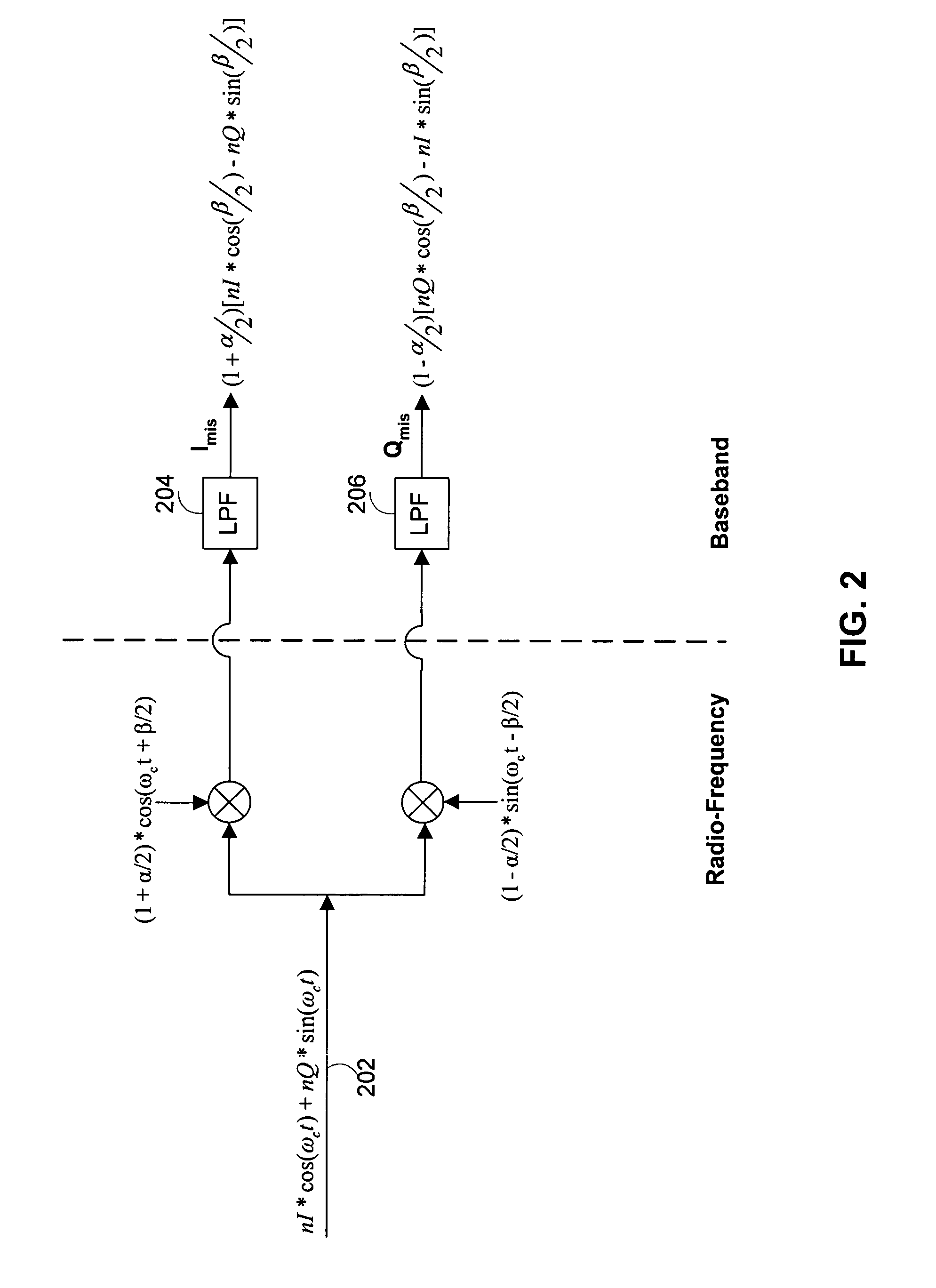
[0036]The disclosed technology provides a communication system and method for handling I / Q mismatch, which can occur in the transmitter and / or the receiver of a communication system. An ideal “I” oscillator and an ideal “Q” oscillator provide periodic signals that are π / 2 radians apart in phase. For ease of explanation and without limiting the scope of the invention, it will be assumed herein that an ideal “I” oscillator provides a cosine signal and an ideal “Q” signal provides a sine signal. Accordingly, I / Q mismatch can be described by an amplitude mismatch of α and / or a phase mismatch of β between the “I” and “Q” oscillators that can be described mathematically by

[0037]Iosc⁡(t)=(1+α2)⁢cos⁡(ωc⁢t+β2),⁢and(EQ1)Qosc⁡(t)=(1-α2)⁢sin⁡(ωc⁢t-β2),(EQ2)

where ωc is the oscillator frequency.

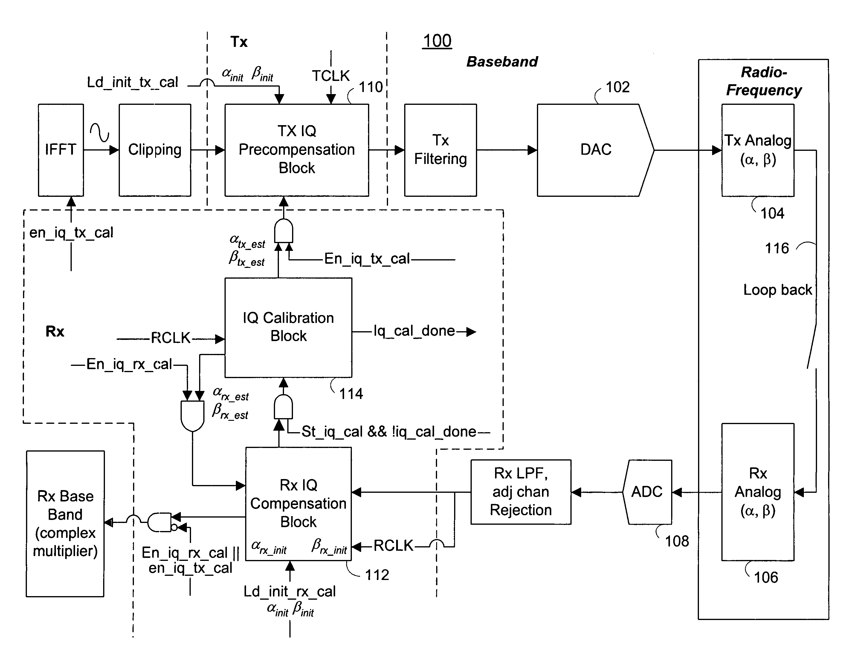
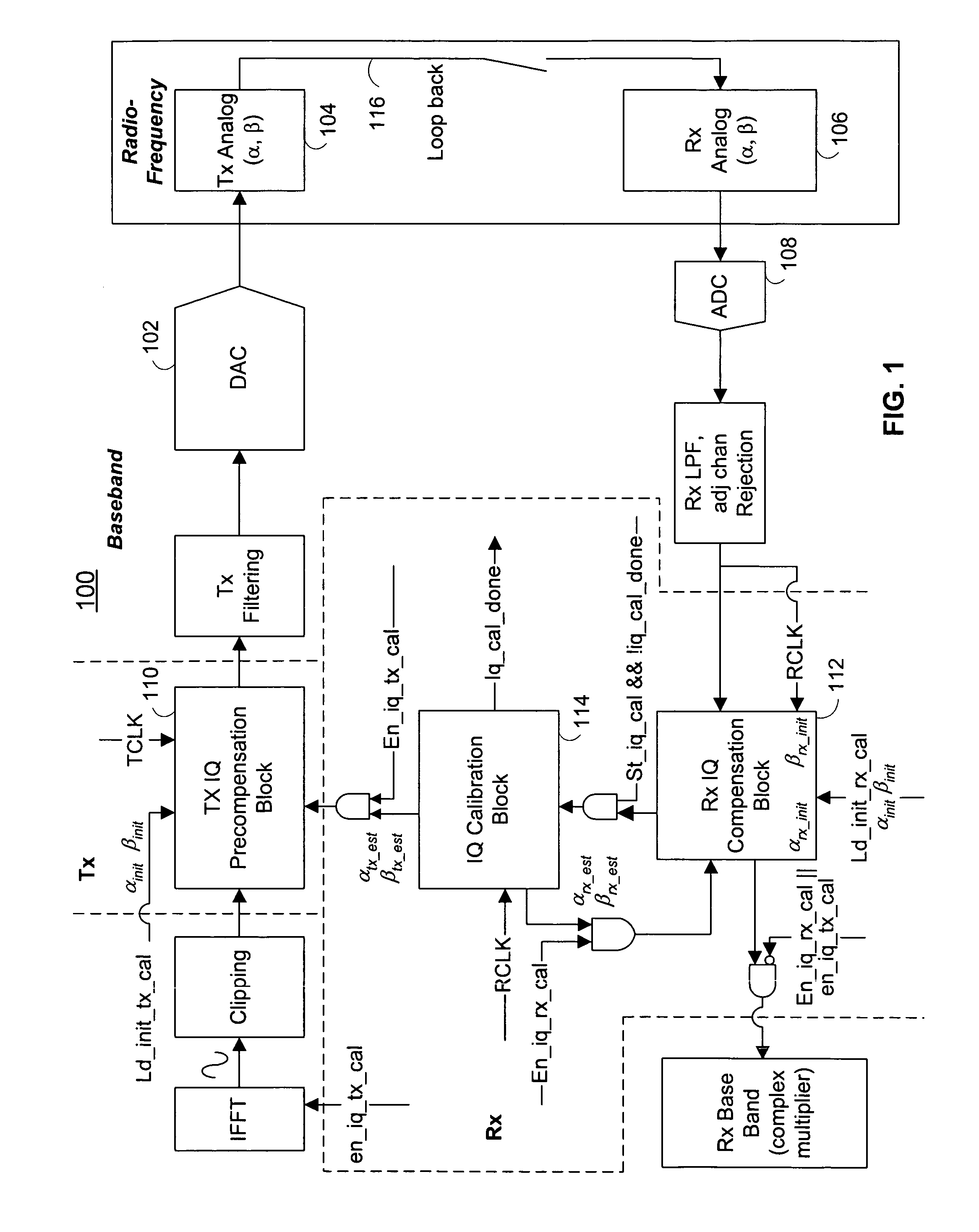
[0038]Referring now to FIG. 1, there is shown a communication system 100 that includes transmitter circuitry and receiver circuitry. The communication system 100 can exist in a communication device such as...


PUM


Abstract

A communications system is provided that includes a detector that has I/Q mismatch, a calibration circuit that estimating a phase and/or an amplitude mismatch of the detector, and a compensation circuit that uses the estimated phase and/or amplitude mismatch to mitigate the effects of the amplitude and/or phase mismatch. An IQ-modulated signal produced by the I/Q-modulator can be communicated over a loop back connection to the detector of the communication system. The calibration circuit can estimate the I/Q mismatch for the IQ-modulator and can provide the estimated values to a pre-compensation circuit. In one aspect, I/Q mismatch in the IQ-modulator of a communication system can be determined using a spectrum analyzer. Power measurements can be used to compute the amplitude mismatch and the phase mismatch of an IQ-modulator.

Description

CROSS-REFERENCE TO RELATED APPLICATIONS[0001]This application claims the benefit under 35 U.S.C. §119(e) of U.S. Provisional Application No. 60 / 672,120, filed Apr. 15, 2005, which is incorporated herein by reference in its entirety.BACKGROUND OF THE INVENTION [0002]Electronic communications using devices such as telephones, fax machines, mobile telephones, radios, and modems generally involve wireline electric signals and / or wireless electromagnetic signals. The study of electronic signals is called signal processing, and the study of communicating signals is called communication theory.[0003]Electronic signals are generally characterized by at least three well-known properties—frequency, amplitude, and phase—any one of which can be used to represent information. For example, AM radio stations use electromagnetic signals that contain information in their amplitudes, and FM radio stations use electromagnetic signals that contain information in their frequencies. In general, the proce...

Claims


Application Information

Patent Timeline
IPC IPC(8): H04L27/00
CPCH04L27/38H04L27/364
Inventor KOPIKARE, RAHULHSU, YUNGPINGNALLAPUREDDY, BHASKAR
Owner MARVELL INT LTD
Why Eureka
Try Eureka