
Nozzle for the discharge of a flowable substance

a flowable substance and nozzle technology, applied in the direction of liquid transfer devices, transportation and packaging, packaging, etc., can solve the problems of irreversible cutting, inability to correct, and no longer use of the nozzle in this way

Active Publication Date: 2010-05-04
HENKEL KGAA
View PDF13 Cites 49 Cited by
  • Summary
  • Abstract
  • Description
  • Claims
  • Application Information

AI Technical Summary

Benefits of technology

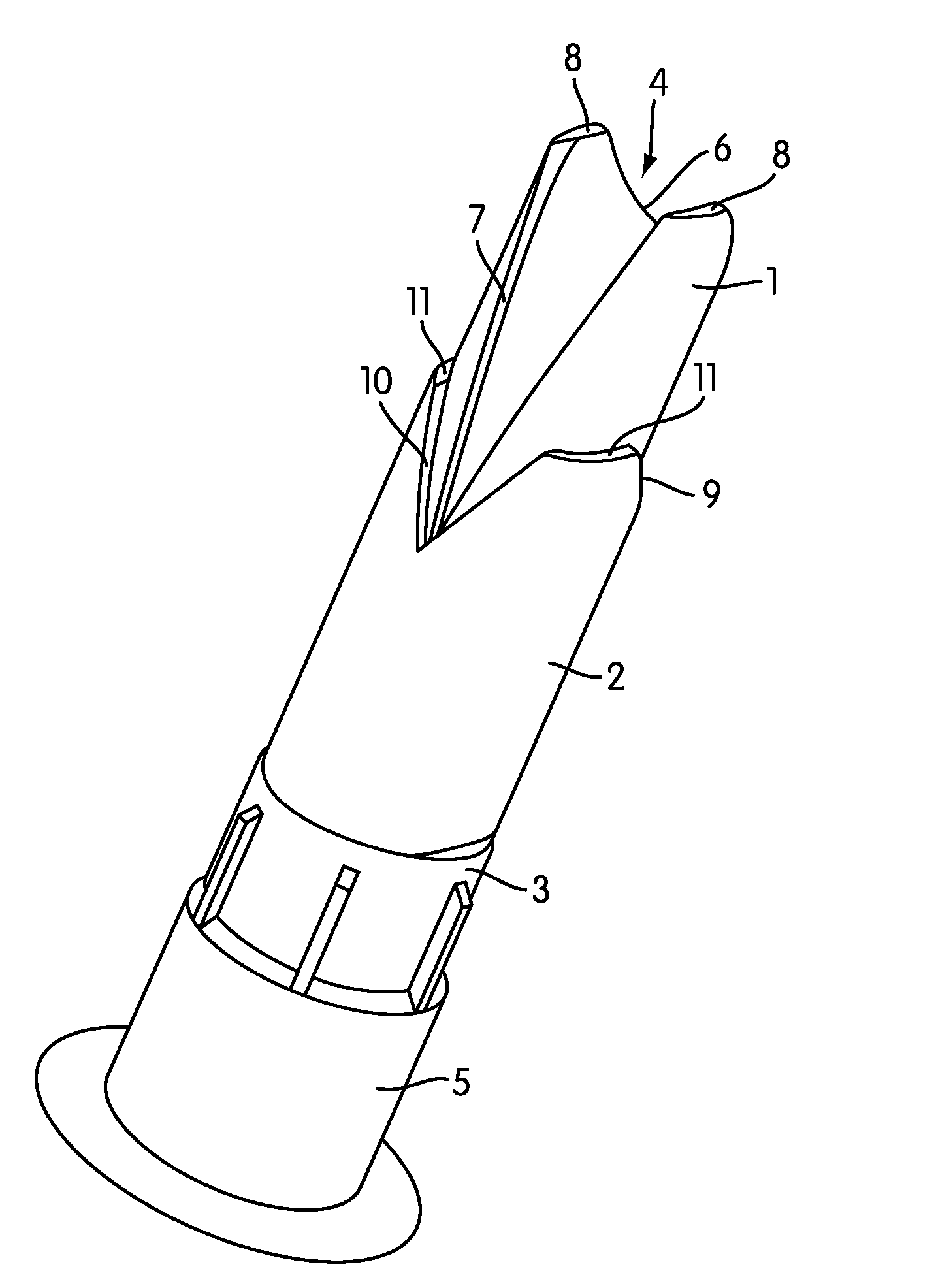
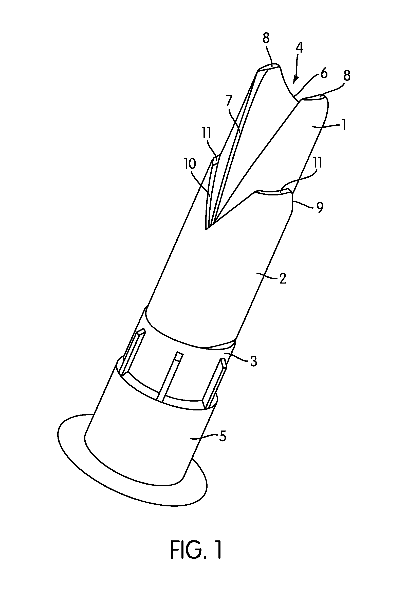
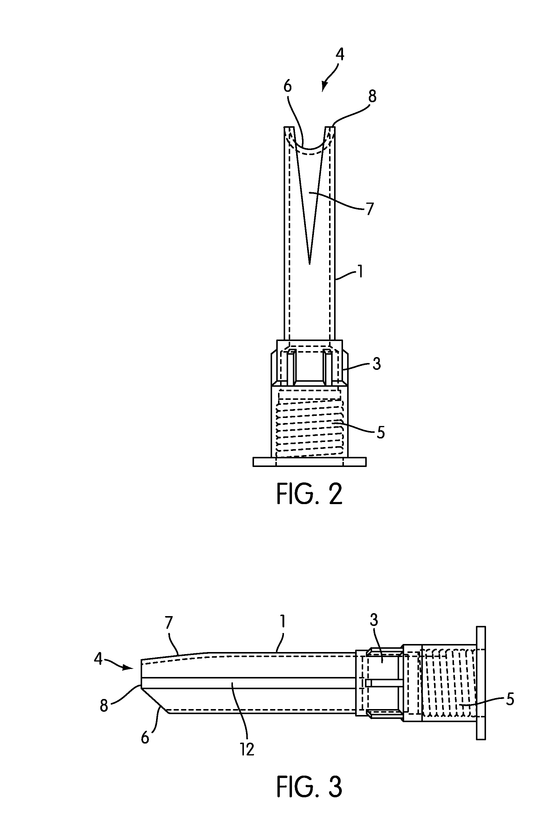
[0011]Preferably, the control element also has its own opening profile. This opening profile should preferably correlate with the opening profile of the orifice. This means that when the orifice possesses for example, a triangular opening profile, then the opening profile of the control element is also preferably triangularly shaped, when these profiles do not also have to be necessarily congruent or similar. In fact, according to a further development of the invention, it is preferred that the angle of opening of the opening profile of the control element is greater than the angle of opening of the opening profile of the orifice. In particular, the opening profile of the orifice can be designed narrower and longer, whereas the opening profile of the control element is formed wider and shorter, therefore deeper, so to speak. Through this, there results a variation possibility, which can be particularly advantageous, in that the dispensed material strand flows preferentially and as fast as possible to the place where it is intended to be placed and consequently, due to the geometry, spreads out in this area in an optimal manner.

Problems solved by technology

In particular, such a cut is irreversible and might not be correctable, if, for example, the opening profile is made too big.
This can lead to the nozzle cut in this way being no longer useable and therefore has to be thrown away and replaced by a new nozzle.
Also, after the first use-tests, the nozzle cut in this way can reveal that it does not, however, have the optimal geometry for the application purpose, with the result that even with a nozzle cut that was initially assumed correct, this nozzle nevertheless has to be replaced by another nozzle.

Method used


Image

  • Nozzle for the discharge of a flowable substance
  • Nozzle for the discharge of a flowable substance
  • Nozzle for the discharge of a flowable substance

Examples


Embodiment Construction

[0006]Accordingly, the invention is based on the object of disclosing a nozzle that can be quickly prepared and optimized for the respective application purpose with little resources.

[0007]According to the invention, this object is achieved by a positionable control element for varying the geometry of the opening of the orifice.

[0008]According to the invention, the nozzle body and the nozzle tip can therefore be relatively approximately pre-cut, which in principal could also be done by a person with little experience and less manual skill, because according to the invention, an control element is provided with which the geometry of the opening of the orifice can also be subsequently varied. In particular, the orifice opening could even turn out to be somewhat too big for the application purpose, because a certain percentage of the orifice could be subsequently covered up by means of the adjusting element. Also, the orifice can even still be optimized by varying the orifice profile a...


PUM

PropertyMeasurementUnit
shapeaaaaaaaaaa
U-shapeaaaaaaaaaa
widthaaaaaaaaaa

Abstract

A nozzle for the discharge of a flowable substances, for example adhesive or sealing compositions, having a discharge orifice with a variable geometry. The adjustable nozzle permits the user to select the optimal discharge profile suited to a particular application of the composition being discharged.

Description

CROSS REFERENCE TO RELATED APPLICATIONS[0001]This application is a continuation under 35 U.S.C. §365(c) and 35 U.S.C. §120 of international application PCT / EP2005 / 009115, filed on Aug. 24, 2005. This application also claims priority under 35 U.S.C. §119 of DE 10 2004 043 111.6, filed Sep. 7, 2004, which is incorporated herein by reference in its entirety.BACKGROUND OF THE INVENTION[0002]The invention relates to a nozzle for the discharge of a flowable substance, preferably a liquid or pasty adhesive and / or sealing compound, in particular for glazing window glasses for motor vehicles. Said nozzle comprises a nozzle tip that is provided with an orifice for the outlet of the substance. The opening thereof has a longitudinal extension in the direction of the nozzle, preferably forming an essentially triangular or V-shaped profile.[0003]A fixed nozzle of this type is disclosed by the German Utility Model G 8625509.6. This Utility Model relates to a nozzle for the production of a special ...

Claims


Application Information

Patent Timeline
Patent Type & Authority Patents(United States)
IPC IPC(8): B05B1/32B29C48/30
CPCB05C17/00516B05C17/005
Inventor MAIER, HANS-JOERGSCHAETZLE, MICHAEL
Owner HENKEL KGAA
Learn More