Pulse arc welding control method and pulse arc welding device

a control method and welding technology, applied in the direction of arc welding apparatus, welding equipment, manufacturing tools, etc., can solve the problem that users using welding machines do not necessarily use welding wires, and achieve the effect of stably performing and preferable shap

Active Publication Date: 2020-09-29
PANASONIC INTELLECTUAL PROPERTY MANAGEMENT CO LTD
View PDF11 Cites 1 Cited by
  • Summary
  • Abstract
  • Description
  • Claims
  • Application Information

AI Technical Summary

Benefits of technology

[0009]This pulse arc welding control method allows the pulse arc welding device to stably perform pulse welding, and provides a bead having a preferable shape.

Problems solved by technology

However, users using welding machines do not necessarily use the welding wire recommended by the welding machine manufacturer.

Method used


Image

  • Pulse arc welding control method and pulse arc welding device
  • Pulse arc welding control method and pulse arc welding device
  • Pulse arc welding control method and pulse arc welding device

Examples


exemplary embodiment 1

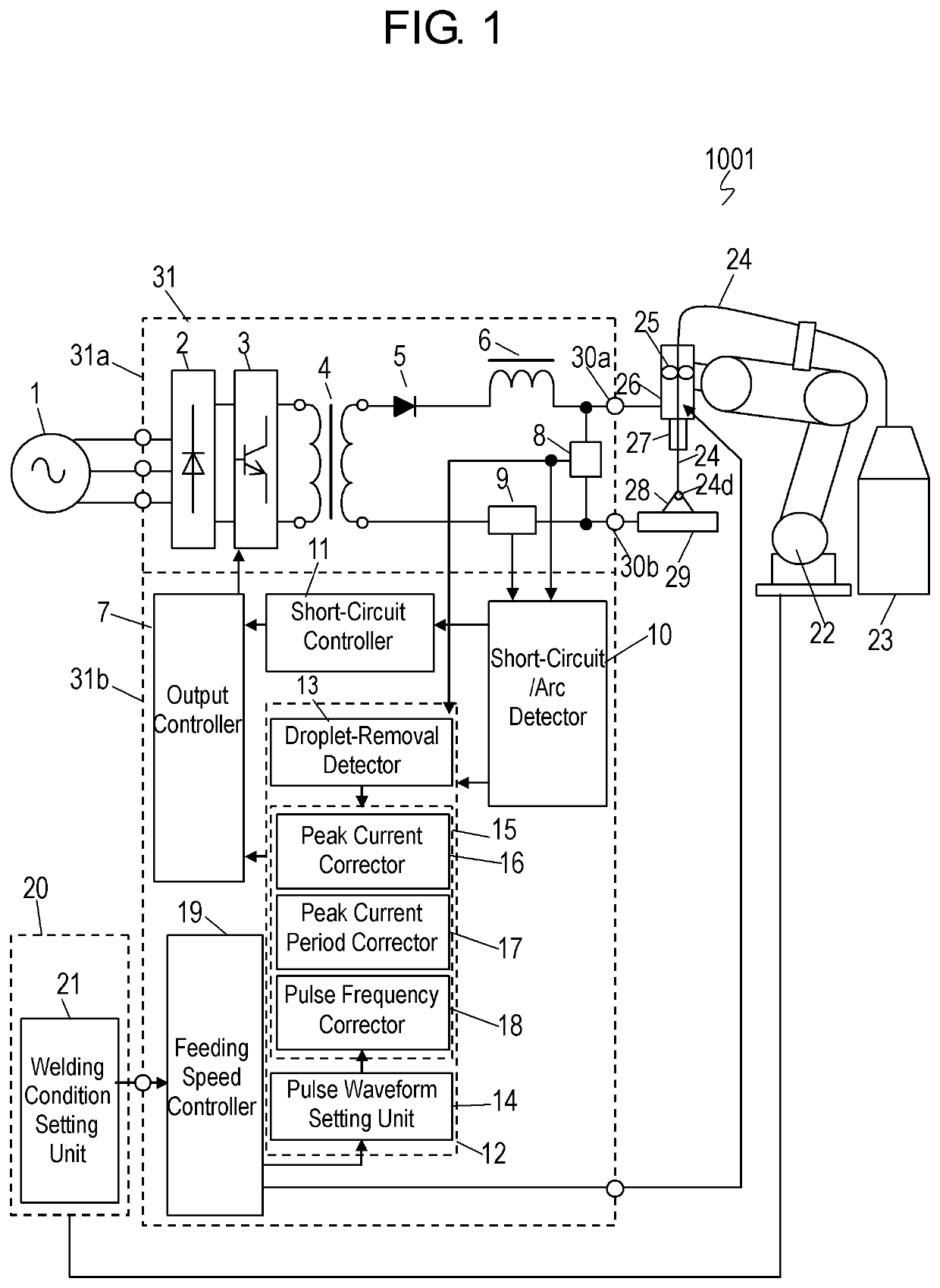
[0022]FIG. 1 is a schematic diagram of pulse arc welding device 1001 according to Exemplary embodiment 1. Pulse arc welding device 1001 includes welding power supply device 31 and robot 22 (manipulator).

[0023]Welding power supply device 31 includes primary rectifier 2 for rectifying an output of input power supply 1, switching element 3 that controls a welding output by controlling an output of primary rectifier 2, transformer 4 for insulating and converting the output from switching element 3 and outputting from secondary side output, secondary rectifier 5 for rectifying an output from the secondary side output of transformer 4, and reactor 6 (DCL) connected in series to secondary rectifier 5. Welding power supply device 31 further includes output controller 7 for driving switching element 3, welding voltage detector 8, and welding current detector 9. Welding power supply device 31 further includes short-circuit / arc detector 10, short-circuit controller 11, and arc controller 12. W...

exemplary embodiment 2

[0097]FIG. 10 is a schematic diagram of pulse arc welding device 1002 according to Exemplary Embodiment 2. In FIG. 10, components identical to those of pulse arc welding device 1001 according to Embodiment 1 illustrated in FIG. 1 are denoted by the reference numerals. Pulse arc welding device 1002 according to Embodiment 2 does not include droplet-removal detector 13 of welding controller 31b of pulse arc welding device 1001 according to Embodiment 1.

[0098]In pulse arc welding device 1002, short-circuit / arc detector 10 detects a short-circuit between welding wire 24 and object 29 based on welding voltage V, thereby detecting that the molten droplet is removed from welding wire 24. In order to eliminate unstable molten droplet transfer state due to different welding conditions, such as welding wire 24 and shielding gas to be used, pulse arc welding device 1002 is designed such that molten droplet transfer state becomes an optimal state. If removal time point td of molten droplet tran...


PUM

PropertyMeasurementUnit
peak current IPaaaaaaaaaa
pulse frequency PHzaaaaaaaaaa
peak current IPaaaaaaaaaa

Abstract

A pulse arc welding device is controlled so as to weld an object by removing, from a welding wire, a molten droplet produced by melting the welding wire by applying a welding voltage between the welding wire and the object and allowing a welding current to flow through the welding wire such that the welding current alternately repeats, at pulse frequency, a peak current period in which the welding current is a peak current and a base current period in which the welding current is a base current smaller than the peak current. A removal time point at which the molten droplet is removed from the welding wire is determined. In a case where the removal time point is not in the base current period, a pulse waveform parameter which is at least one of the peak current and the peak current period is adjusted, and the pulse frequency based on a predetermined relationship between the pulse frequency and the pulse waveform parameter is adjusted so as to cause the removal time point to be in the base current period. This method allows a stable pulse arc welding.

Description

CROSS-REFERENCE TO RELATED APPLICATIONS[0001]This application is a U.S. national stage application of the PCT international application No. PCT / JP2016 / 005226 filed on Dec. 27, 2016, which claims the benefit of foreign priority of Japanese patent application No. 2016-009420 filed on Jan. 21, 2016, the contents all of which are incorporated herein by reference.TECHNICAL FIELD[0002]The present invention relates to a pulse arc welding control method and a pulse arc welding device for performing a pulse arc welding while feeding a welding wire which is a consumable electrode.BACKGROUND ART[0003]In a conventional pulse arc welding machine, it is common to build a database of welding conditions suitable for each material, such as mild steel and stainless steel, with the welding wire recommended by each welding machine manufacturer individually. For example, in a case of a pulse waveform, parameters, such as peak current, base current, pulse frequency, are adjusted while each operator of th...

Claims


Application Information

Patent Timeline
Patent Type & Authority Patents(United States)
IPC IPC(8): B23K9/173B23K9/095B23K9/09
CPCB23K9/09B23K9/095B23K9/173B23K9/073
Inventor FUJIWARA, JUNJI
Owner PANASONIC INTELLECTUAL PROPERTY MANAGEMENT CO LTD
Why Eureka
Try Eureka