[0009]It is the primary object of this invention to provide a fluid-level sensing device that is easily and promptly attached to a fluid-collecting pan in a desired position of use that places its pivoting float body near the base of the pan's perimeter wall, operates for extended periods of time with little or no post-installation inspection or maintenance, and when properly installed is able to rapidly, reliably, and repeatedly send electrical signals to an associated fluid-producing system to shut it off when only a small threshold amount of fluid has accumulated in the pan. It is a further object of this invention to provide a fluid-level sensing device that is configured for sturdy mounting to a pan wall so that little or no deviation from its originally installed position relative to the pan is experienced during extended periods of use. It is also an object of this invention to provide a fluid-level sensing device that is made from corrosion-resistant materials that
resist premature deterioration and malfunction. A further object of this invention is to provide a fluid-level sensing device capable of proper and reliable operation when subjected to temperature extremes. It is also an object of this invention to provide a fluid-level sensing device that can be immediately and easily tested by an installer or maintenance personnel for certainty that the device is properly operational in the intended application. It is a further object of this invention to provide a fluid-level sensing device configured to facilitate its association with the perimeter wall of a fluid-collection pan, shorten installation time, and permit optional adjustment of float body distal end deployment height. It is also an object of this invention to provide a fluid-level sensing device having a rugged construction and being made from materials that do not experience performance loss as a result of
exposure to widely fluctuating temperature variations. It is also an object of this invention to permanently or detachably incorporate a fluid-level sensing device as a part of a unitary switch and drain line connection
assembly configured for easy and proper installation of the fluid-level sensing device simply as a result of drain line connection. It is a further object of this invention to provide a fluid-level sensing device that provides adequate venting to prevent float body
airlock malfunction, facilitates fluid entry into the open-bottomed lower chamber of its float / switch housing, and reduces entry of airborne debris into the lower chamber of the float / switch housing, including the loose insulation fibers typically encountered in attics with some air conditioning applications. It is a further object of this invention to incorporate structure that substantially reduces or avoids lean-in of fluid-collection pan walls at the site of present invention installation and otherwise promotes fast and reproducible shut-off responses directed to an associated fluid-producing unit when the
fluid level in the pan exceeds a pre-established threshold level considered safe.
[0010]The present invention, when properly made and used, will provide a fluid-level sensing device for use in combination with an associated collection tray or pan (often simply referred to herein as “pan” for simplicity of description and without any intent of limitation) to collect fluid and shut off the source of fluid production when the amount of collected fluid exceeds a pre-established threshold level considered safe to prevent damage to the fluid source and / or its surroundings. Potential applications of the present invention can include the monitoring of condensates collected as a result of air conditioning and furnace system operation (to prevent back-up damage to the system and / or overflow damage to surroundings), as well as the monitoring of other potential fluid risk hazards, such as but not limited to potential hot
water heater malfunction. The present invention fluid-sensing device is often provided as a part of a unitary switch / drain-line connection
assembly that can be easily handled by an installer to achieve rapid mounting to the perimeter wall of a fluid-collection pan in association with a pre-formed drain line opening in the perimeter wall. Attachment to the drain-line connection assembly can be permanent, temporary, or quick-release. In the alternative, the present invention may be pre-installed during pan manufacture, leaving only a simple and optional float
body height adjustment for the installer at the time of pan installation and pan leveling to ensure repeatable and reproducible float body deployment during long-term use whereon little routine inspection or maintenance will be needed.
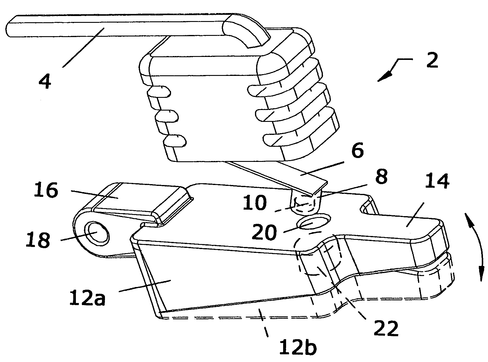
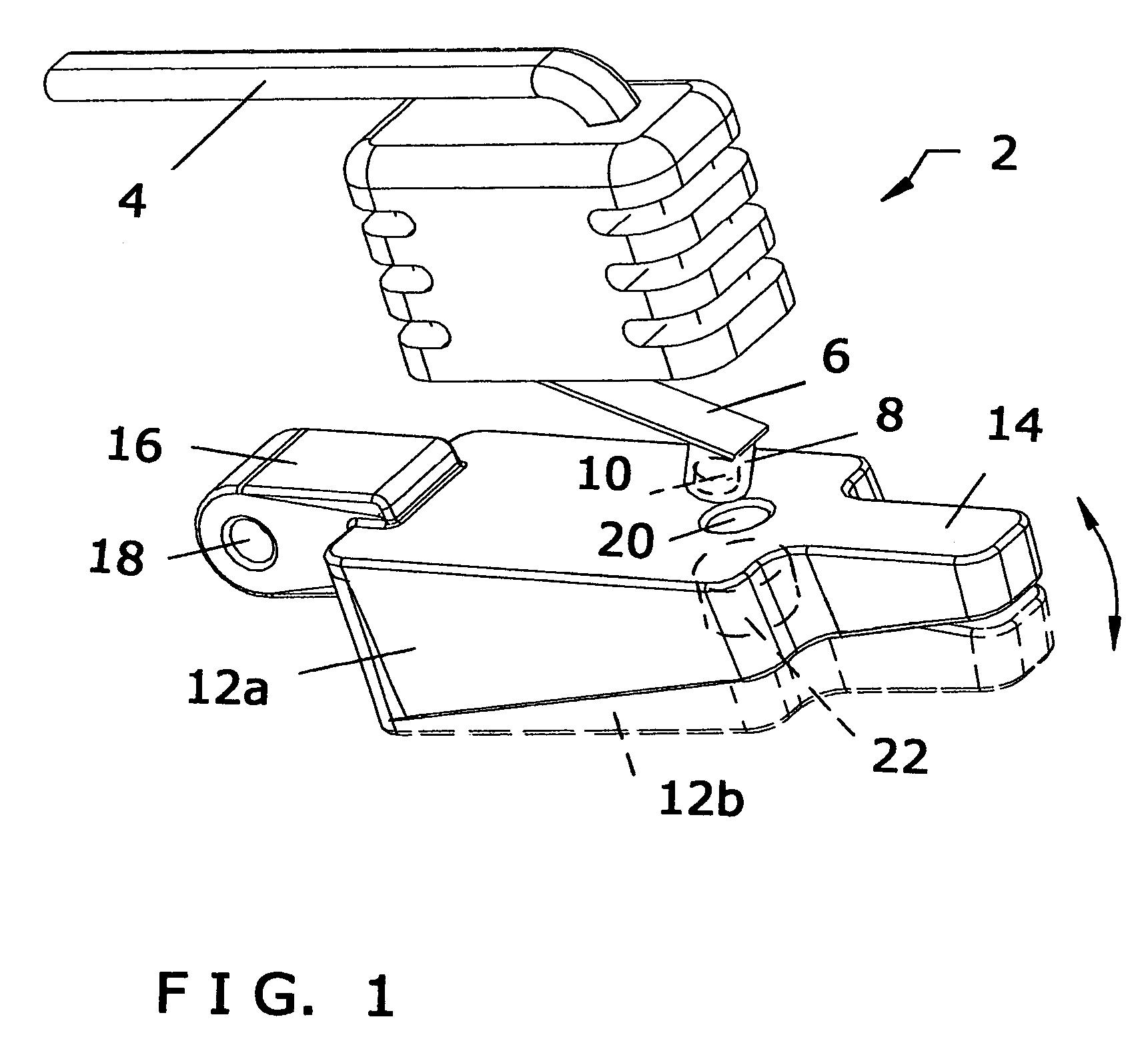
[0011]The present invention comprises a reliable fluid-level sensing device that uses the interaction of a first magnet attached to the distal end of an external micro switch arm and a second (typically larger) magnet positioned within the distal end of a pivoting float body to provide interaction of one to the other so as to trigger the snap action mechanism within the micro switch needed to close a circuit and send a shut-off
signal to the fluid-producing unit to stop its fluid production. A single housing is used to place a corrosion-resistant encapsulated micro switch in an open-topped upper chamber in an isolated position above an open-bottomed lower chamber in which a pivoting float body moves in response to rising and falling fluid levels, with the magnetic forces acting through the float / switch housing's central wall, the bottom surface of a magnet-housing cup when used on the external arm of the micro switch, the top surface of the float body, and any other magnet-positioning materials that are placed between the two interacting magnets. After float body deployment takes place that causes
tripping of the micro switch, manual reset of the float body is accomplished via its lever-like distal end, which can also be used quickly by an installer as a finger latch to test the float body and make certain that a newly installed fluid-sensing present invention device is fully operational to meet application requirements. Attraction or repulsion forces between the two magnets can be the triggering factor. The open-bottomed lower chamber in the float / switch housing is substantially filled by the buoyant float body. Also, there is no opening in the housing between the lower open-bottomed float body chamber and the upper chamber in which the micro switch is located to prevent direct fluid communication from the lower chamber into the upper chamber. In addition, the main body of the micro switch is completely encapsulated in waterproof material to further protect it from corrosion and enhance its reliability for long-term use, and one or more seals are typically used to secure the micro switch within the upper chamber and reduce the likelihood of fluid entry into the upper chamber from above.
Electrical wiring extending in an upwardly direction from the micro switch connects it to the fluid-producing system for which monitoring is required, so that when the
fluid level in a pan to which the present invention is attached exceeds a pre-determined threshold level considered safe, the rising fluid causes the distal end of the float body to pivot in an upwardly direction and increase
magnetic interaction between the magnet it supports and the second magnet associated with the distal end of the micro switch arm, which when the threshold level is reached causes a circuit to be closed and results in an
electric signal being sent to the fluid-producing system to shut it off and prevent overflow damage to the system, surrounding equipment, nearby objects, and / or adjacent materials.
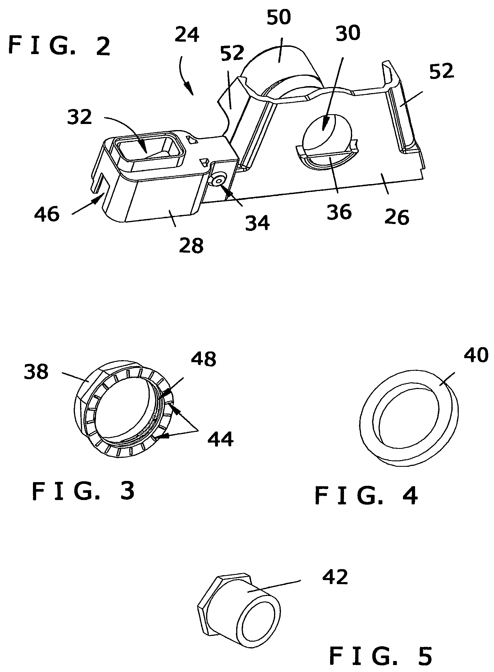
[0012]It is also preferred for the float housing to have venting that prevents
airlock malfunction of the float body. The slot used to guide the lever-like distal end of the float body during its deployment can be configured to serve as an effective air vent. In addition, several alternative mounting means for fast and secure connection of the present invention float / switch housing to a fluid-collecting pan are contemplated, including but are not limited to, the connection of a substantially trapezoidal-shaped mounting plate between the float / switch housing and a complementary trapezoidal-shaped shelf area pre-molded into the perimeter wall of the fluid collection pan for drain line connection, a quickly-releasable spring tab connection between the float / switch housing and a mounting ring with a depending spring tab housing having a rail plate, the connection of the float / switch housing via a bridge to a substantially trapezoidal-shaped mounting plate complementary in configuration to a trapezoidal-shaped shelf area integrated into the pan wall that permits pre-leveled float / switch housing installation relative to the pan, and a grooved spring tab and
fastener connection of the float / switch housing to a spring tab housing with complementary ridges that depends from a substantially trapezoidal-shaped mounting plate or a bridge depending from a substantially trapezoidal-shaped mounting plate. When mounting plate of the present invention has a configuration complementary to that of the shelf area pre-molded into the pan, such as but not limited to the substantially trapezoidal shape mentioned above, the act of drain line connection using the shelf area provides immediate leveling of the float body relative to the pan, so that once leveling of the pan is achieved the resulting float deployment trouble-free, reliable, and reproducible without malfunction during long-term use. Contemplated applications include, but are not limited to, use in air conditioning and furnace system condensate collection / overflow prevention applications for shutting off an air conditioning system or furnace when collected condensate in a pan beneath the portion of the system at risk for fluid damage exceeds a pre-established threshold amount, as well as other applications including where rising condensate / fluid beyond a safe threshold limit is undesirable and automated shut-off of the condensate / fluid source is needed or desired to eliminate back-up damage to the condensate producing system or the risk of damage to surrounding objects and structures.

