Method of calibrating a fluid-level measurement system

Active Publication Date: 2010-05-04
NASA
View PDF50 Cites 12 Cited by
  • Summary
  • Abstract
  • Description
  • Claims
  • Application Information

AI Technical Summary

Problems solved by technology

However, if the fuel-level measurement system is sensitive to the type of fuel being used, the measurement system must be calibrated to accommodate a particular type of fuel.

Method used


Image

  • Method of calibrating a fluid-level measurement system
  • Method of calibrating a fluid-level measurement system
  • Method of calibrating a fluid-level measurement system

Examples


Embodiment Construction

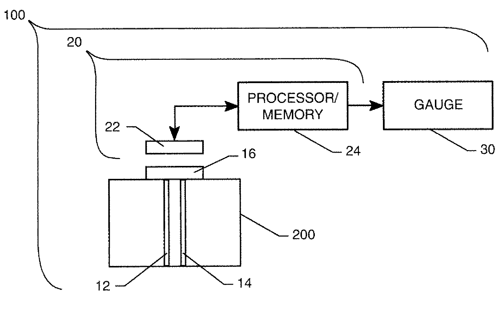
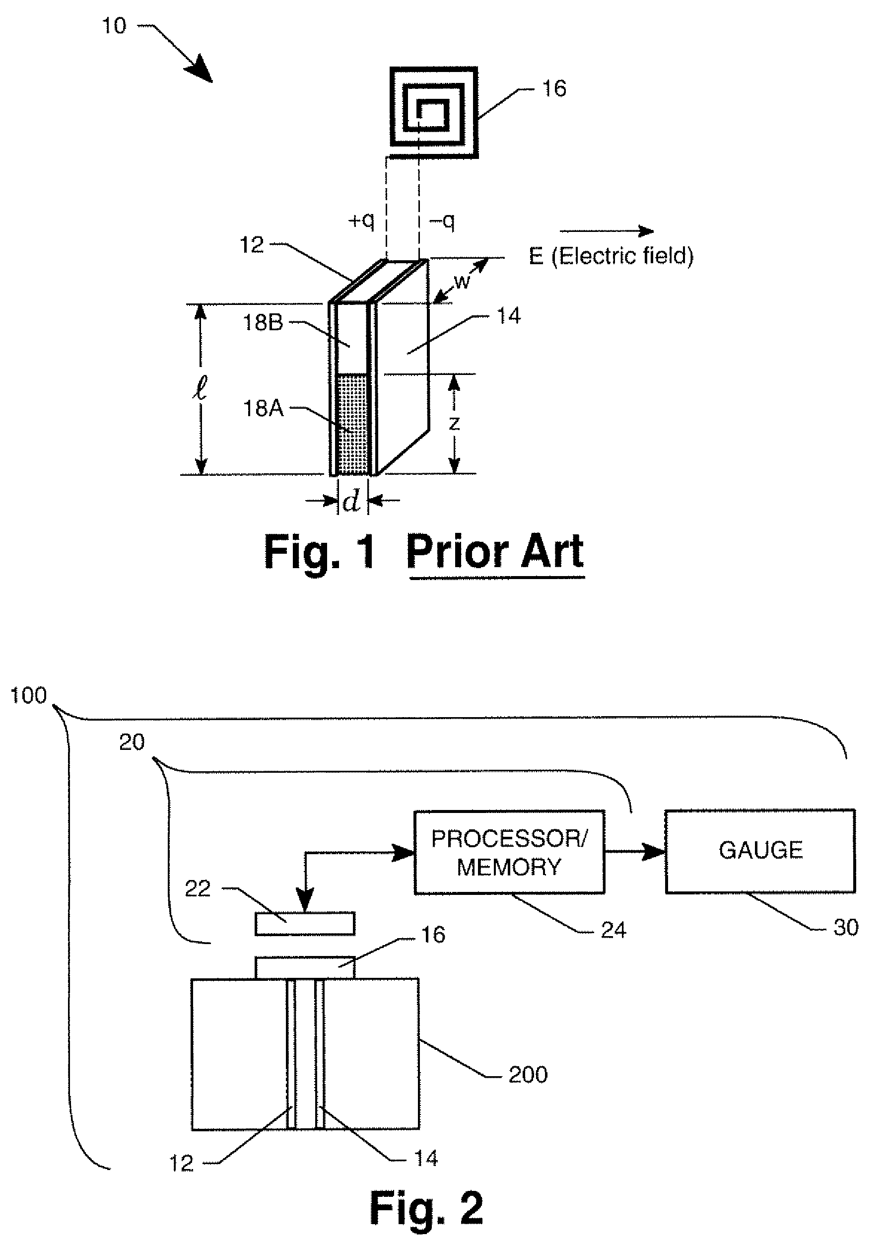
[0012]Prior to describing the calibration method of the present invention, some background will be presented for a recently-developed fluid-level measurement system that can be calibrated in accordance with the present invention. The fluid-level measurement system is a wireless system in that the systems' sensor(s) are powered and interrogated in a wireless fashion. As a result of such powering / interrogation, the systems' sensor(s) generate a frequency response. The sensors can be any of the following:

[0013](i) a fluid-level capacitance sensor with an inductor coupled thereto as disclosed in U.S. Pat. Nos. 7,086,593, 7,159,774 and 7,255,004, the contents of each being hereby incorporated by reference in their entirety, or

[0014](ii) a fluid-level sensor that is defined by a conductor formed into a geometric pattern such as a spiral trace as disclosed in U.S. patent application Ser. No. 11 / 671,089, filed Feb. 5, 2007, the contents of which are hereby incorporated by reference in their...


PUM


Abstract

A method of calibrating a fluid-level measurement system is provided. A first response of the system is recorded when the system's sensor(s) is (are) not in contact with a fluid of interest. A second response of the system is recorded when the system's sensor(s) is (are) fully immersed in the fluid of interest. Using the first and second responses, a plurality of expected responses of the system's sensor(s) is (are) generated for a corresponding plurality of levels of immersion of the sensor(s) in the fluid of interest.

Description

ORIGIN OF THE INVENTION[0001]This invention was made in part by an employee of the United States Government and may be manufactured and used by or for the Government of the United States of America for governmental purposes without the payment of any royalties thereon or therefor. Pursuant to 35 U.S.C. §119, the benefit of priority from provisional application 60 / 908,698, with a filing date of Mar. 29, 2007, is claimed for this non-provisional application.BACKGROUND OF THE INVENTION[0002]1. Field of the Invention[0003]This invention relates to calibration of fluid-level measurement systems. More specifically, the invention is an in-situ method for calibrating a fluid-level measurement system that measures the capacitance or frequency of a response that is correlated to level of a fluid of interest where the calibration is accomplished non-manually without knowledge of the dielectric value of the fluid of interest, the physical properties of the fluid or the physical properties of th...

Claims


Application Information

Patent Timeline
Patent Type & Authority Patents(United States)
IPC IPC(8): G01F25/00G01F1/00
CPCG01F23/266G01F25/0061G01F23/268G01F25/20
Inventor WOODARD, STANLEY E.TAYLOR, BRYANT D.
Owner NASA
Why Eureka
Try Eureka