System to increase capacity of LNG-based liquefier in air separation process

a technology of air separation and liquefier, which is applied in cold treatment separation, container discharging methods, solidification, etc., can solve the problems of product transportation cost penalties, capital costs are particularly sensitive, and the increase in capital costs does not begin to pay off, so as to increase the capacity of lng-based liquefiers

Inactive Publication Date: 2010-05-11
AIR PROD & CHEM INC
View PDF13 Cites 18 Cited by
  • Summary
  • Abstract
  • Description
  • Claims
  • Application Information

AI Technical Summary

Benefits of technology

[0021]The present invention relates to a cryogenic air separation unit which utilizes an LNG-based liquefier to provide the refrigeration necessary when at least a portion of the product is desired as liquid. The present invention is a system to increase the capacity of the LNG-based liquefier wherein, in a low production mode, the nitrogen that is fed to the LNG-based liquefier consists only of at least a portion of the high pressure nitrogen from the distillation column system while in a high production mode, a supplemental compressor is used to boost the pressure of at least a portion of the low pressure nitrogen from the distillation column system to create additional (or replacement) feed to the LNG-based liquefier. A key to the present invention is the supplemental compressor is separate and distinct from the LNG-based liquefier. This allows its purchase to be delayed until a capacity increase is actually needed and thus avoid building an oversized liquefier based on a speculative increase in liquid product demand.

Problems solved by technology

A problem with this oversizing approach however is the incremental capital cost incurred does not begin to pay off until the projected demand increase is actually realized (if at all).
Furthermore, capital costs are particularly sensitive for LNG-based liquefiers since, as opposed to conventional liquefiers which are typically located near the customers of the liquid products, LNG-based liquefiers must be located near an LNG receiving terminal and thus incur a product transportation cost penalty.
However, only modest capacity increases can be achieved in this manner.
First, the LNG is not sufficiently cold to liquefy a low-pressure nitrogen gas.

Method used


Image

  • System to increase capacity of LNG-based liquefier in air separation process
  • System to increase capacity of LNG-based liquefier in air separation process
  • System to increase capacity of LNG-based liquefier in air separation process

Examples


example

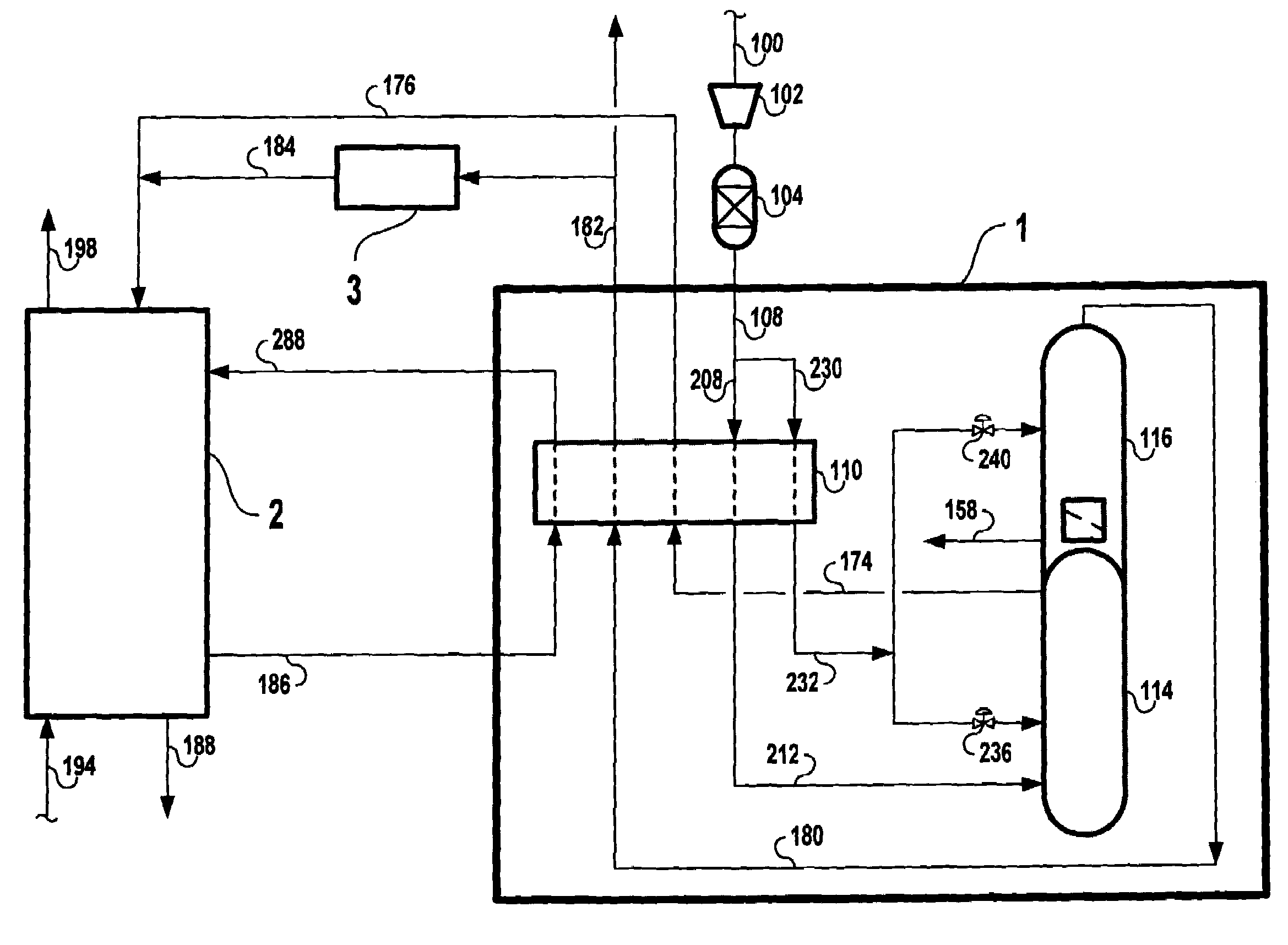
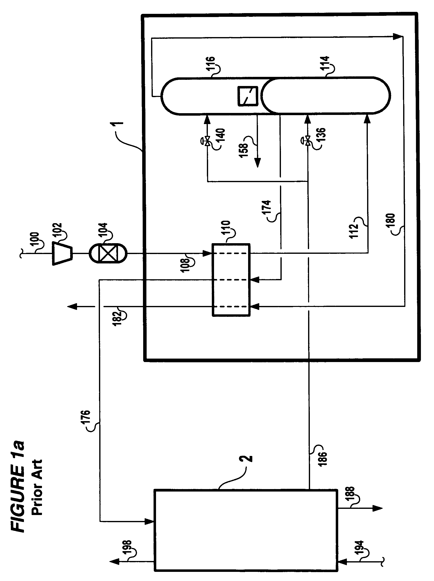
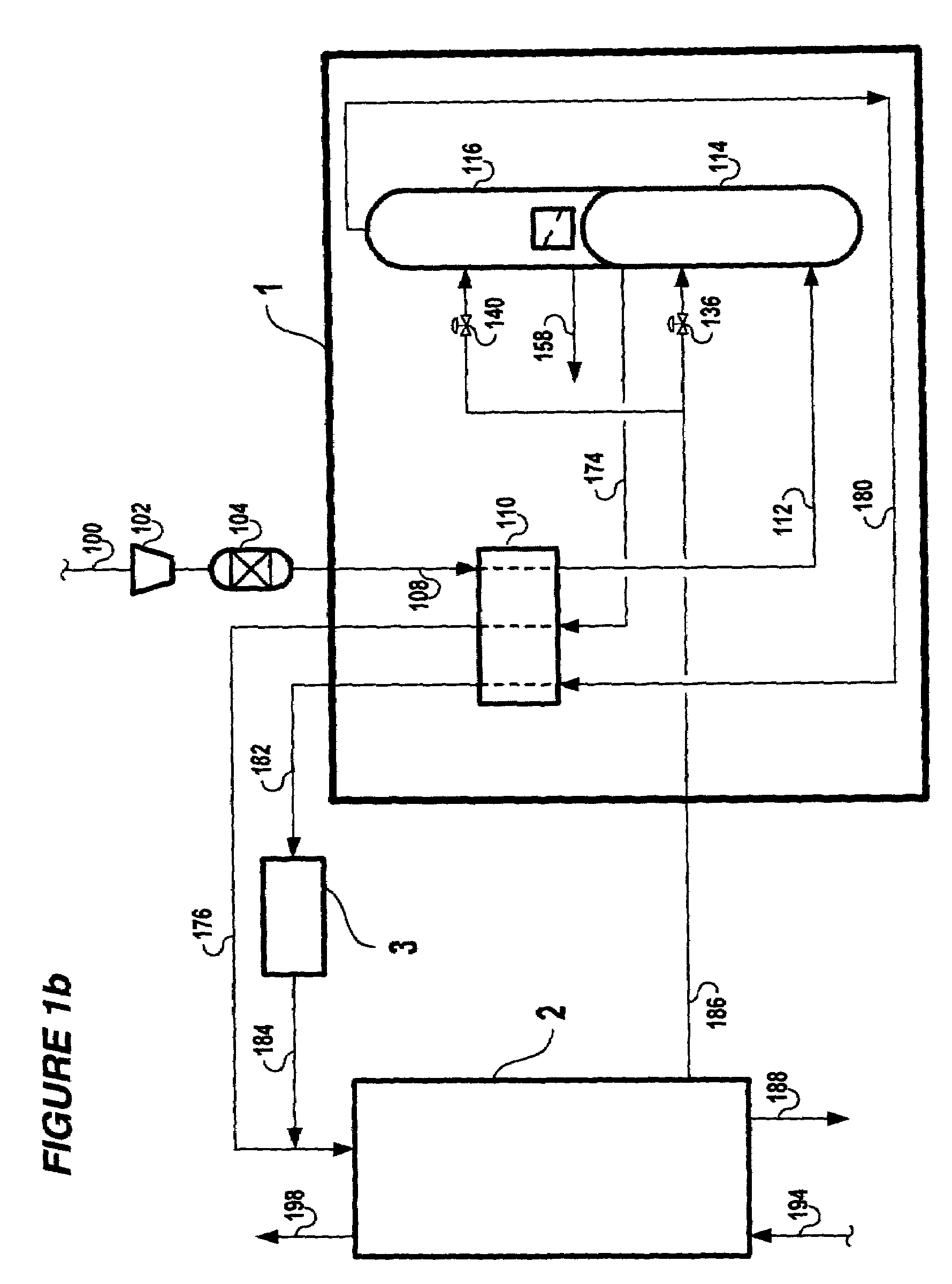
[0049]A worked example has been prepared to demonstrate possible operating conditions associated with the present invention and clarify what is different and common between operating modes. Three cases will be given: Case 1 corresponds to low production mode operation without the supplemental processing unit (3) while Cases 2 and 3 correspond to high production mode operation with the supplemental processing unit (3) in place. For this example, Case 1 is depicted by the LNG-based liquefier (2) of FIG. 3a; Cases 2 and 3 are depicted by the LNG-based liquefier (2) and the supplemental processing unit (3) of FIG. 3b. For Cases 2 and 3, referring to FIG. 3b, valve 380 is closed and valve 382 is open. The cryogenic ASU in shown in greater detail in FIG. 4 and described below.

[0050]Referring to FIG. 4, atmospheric air 100 is compressed in the main air compressor 102, purified in adsorbent bed 104 to remove impurities such as carbon dioxide and water, then divided into two fractions: strea...


PUM


Abstract

A system is set forth to increase the capacity of an LNG-based liquefier in a cryogenic air separation unit wherein, in a low production mode, the nitrogen that is fed to the LNG-based liquefier consists only of at least a portion of the high pressure nitrogen from the distillation column system while in a high production mode, a supplemental compressor is used to boost the pressure of at least a portion of the low pressure nitrogen from the distillation column system to create additional (or replacement) feed to the LNG-based liquefier. A key to the present invention is the supplemental compressor and the associated heat exchange equipment is separate and distinct from the LNG-based liquefier. This allows its purchase to be delayed until a capacity increase is actually needed and thus avoid building an oversized liquefier based on a speculative increase in liquid product demand.

Description

BACKGROUND OF THE INVENTION[0001]The present invention concerns the well known process (hereafter “Process”) for the cryogenic separation of an air feed wherein:[0002](a) the air feed is compressed, cleaned of impurities that will freeze out at cryogenic temperatures such as water and carbon dioxide, and subsequently fed into an cryogenic air separation unit (hereafter “ASU”) comprising a main heat exchanger and a distillation column system;[0003](b) the air feed is cooled (and optionally at least a portion condensed) in the main heat exchanger by indirectly heat exchanging the air feed against at least a portion of the effluent streams from the distillation column system;[0004](c) the cooled air feed is separated in the distillation column system into effluent streams including a stream enriched in nitrogen and a stream enriched in oxygen (and, optionally, respective streams enriched in the remaining components of the air feed including argon, krypton and xenon); and[0005](d) the d...

Claims


Application Information

Patent Timeline
Patent Type & Authority Patents(United States)
IPC IPC(8): F25J1/00F17C9/02F25J3/00
CPCF25J1/0015F25J1/0224F25J1/0234F25J1/0245F25J1/0264F25J1/0292F25J3/0406F25J3/04224F25J3/04266F25J3/04272F25J3/04351F25J3/04412F25J3/04678F25J3/04812F25J3/04969F25J1/004F25J2245/42F25J2210/02F25J2210/62F25J2230/08F25J2230/42F25J3/00
Inventor DEE, DOUGLAS PAULCHOE, JUNG SOOHERRON, DONN MICHAEL
Owner AIR PROD & CHEM INC
Why Eureka
Try Eureka