
Doppler type ultrasonic flowmeter, flow rate measuring method using doppler type ultrasonic flowmeter and flow rate measuring program used in this doppler type ultrasonic flowmeter

a flow rate measurement and ultrasonic flow technology, which is applied in the direction of ultrasonic/sonic/infrasonic diagnostics, instruments, and using reradiation, etc., can solve the problems of irregular flow measurement results, inability to measure the flow-speed distribution over the entire tube, and irregular measurement results of flow

Inactive Publication Date: 2010-05-11
THE TOKYO ELECTRIC POWER CO INC +1
View PDF11 Cites 11 Cited by
  • Summary
  • Abstract
  • Description
  • Claims
  • Application Information

AI Technical Summary

Benefits of technology

The present invention provides a doppler ultrasonic flowmeter that can accurately measure the flow of fluid in a tube with minimal interference from the tube wall. The flowmeter includes an ultrasonic transmission member for casting ultrasonic pulses onto the fluid, a flow-speed distribution measurement unit for receiving the reflected ultrasonic pulses and measuring the flow-speed distribution of the fluid, a flow measurement unit for measuring the flow of the fluid based on the flow-speed distribution, and a frequency selecting / setting member for automatically selecting the optimum frequency for resonant transmission. The flowmeter can adjust the incident angle of the ultrasonic pulses to optimize the resonant transmission. Additionally, the flowmeter can include a velocity-vector calculating member and a flow-speed vector calculating member for accurately calculating the flow-speed distribution and the velocity vectors of the fluid. These features make the flowmeter more reliable and accurate for measuring fluid flow in a tube.

Problems solved by technology

Accordingly, in some cases, extremely unstable flow of the fluid which is to be measured leads to irregularities in the measurement results of the flow-speed distribution due to irregularities in density of bubbles or the like.
Accordingly, such irregularities in the flow-speed distribution affect computation of the flow, resulting in irregularities in the measurement results of the flow, as well.
Accordingly, with the conventional doppler ultrasonic flowmeter employing such a channel distance, the maximum distance of the measurement line matches 128 times the minimum channel distance, leading to a problem that measurement of the flow-speed distribution cannot be made over the entire tube in a case wherein the fluid tube is formed with a greater diameter than the aforementioned measurement line.
Accordingly, conventional doppler ultrasonic flowmeters require preliminary measurement for determining the optimum settings suitable for the object which is to be measured, which is troublesome.
This leads to low evaluation of ease of use, although the conventional doppler ultrasonic flowmeter has the advantage of making measurement while suppressing error without “flow correction coefficients”.
However, such a configuration is undesirable from the perspective of design, costs, and the like.
However, such configuration is restricted by the performance of the hardware, costs, and so forth, from the perspective of responsibility of the measurement of the flow which changes in a short period of time.
Even if the problems of the hardware performance and costs are solved in the future, such configuration is undesirable since such configuration is overspeced for the measurement range in which measurement can be made with the conventional doppler ultrasonic flowmeters.
However, such configuration has a problem that determination cannot be made whether or not a backward flow occurs.

Method used


Image

  • Doppler type ultrasonic flowmeter, flow rate measuring method using doppler type ultrasonic flowmeter and flow rate measuring program used in this doppler type ultrasonic flowmeter
  • Doppler type ultrasonic flowmeter, flow rate measuring method using doppler type ultrasonic flowmeter and flow rate measuring program used in this doppler type ultrasonic flowmeter
  • Doppler type ultrasonic flowmeter, flow rate measuring method using doppler type ultrasonic flowmeter and flow rate measuring program used in this doppler type ultrasonic flowmeter

Examples


first embodiment

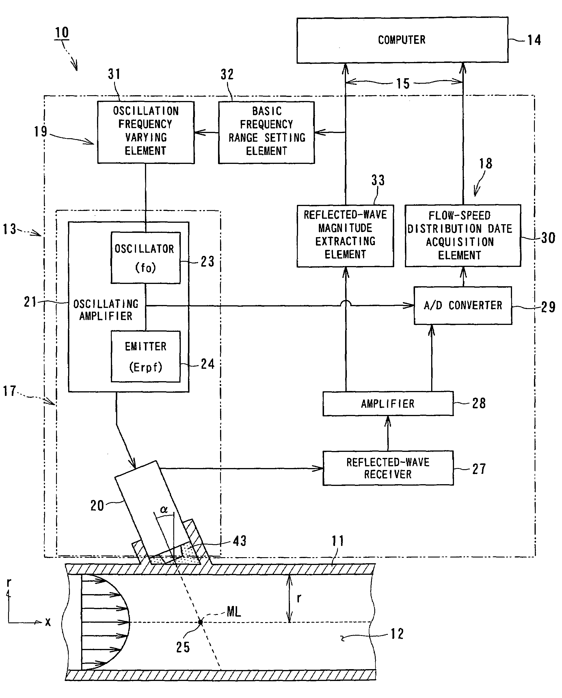
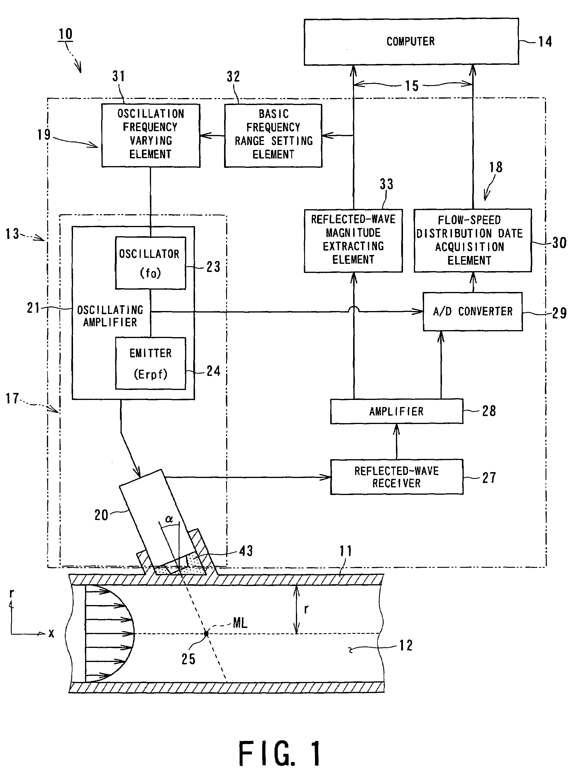
[0147]FIG. 1 is a schematic diagram which shows a schematic configuration of a doppler ultrasonic flowmeter 10 according to a first embodiment of the present invention.

[0148]The doppler ultrasonic flowmeter 10 has a configuration for measuring the flow-speed distribution of a fluid 12 (liquid or gas) which is to be measured, flowing within a fluid tube 11, thereby enabling real-time measurement of the flow over time. The doppler ultrasonic flowmeter 10 comprises an ultrasonic flow-speed distribution data acquisition unit (which will be referred to as “Udflow unit” hereafter) 13 for making measurement of the flow speed of the fluid 12 to be measured, flowing within the fluid tube 11, in a non-contact manner, and a computer 14 for computing the flow-speed distribution of the fluid 12 to be measured based upon the electric signals (data) received from the Udflow unit 13 in order to calculate the flow of the fluid 12 to be measured, and displaying the measurement results thus obtained o...

second embodiment

[0167]FIG. 3 is a schematic diagram which shows a schematic configuration of a doppler ultrasonic flowmeter 50 according to a second embodiment of the present invention.

[0168]The doppler ultrasonic flowmeter 50 has a configuration for improving the signal-to-noise (which will be abbreviated to “S / N” hereafter) ratio of the reflected waves, but having no function for selecting and setting the optimum frequency of the ultrasonic pulses cast into the fluid tube 11.

[0169]In order to improve the S / N ratio of the reflected waves, an arrangement may be made wherein the wall thickness of the fluid tube 11 is adjusted such that resonant transmission occurs. However, such a configuration for adjusting the wall thickness of the fluid tube 11 is far from practical. With the present embodiment, the mounting angle of the ultrasonic transducer 20 is adjusted, thereby achieving the same effects as with the aforementioned configuration for adjusting the wall thickness of the fluid tube 11.

[0170]The ...

third embodiment

[0181]FIG. 4 through FIG. 6 are a schematic diagrams which show a schematic configuration of a doppler ultrasonic flowmeter 60 according to a third embodiment of the present invention.

[0182]As shown in FIG. 4, the doppler ultrasonic flowmeter 60 calculates the velocity component V2 of the fluid 12 to be measured, which flows within the flow tube 11, in the ultrasonic incident angle (ultrasonic emission angle) direction, using the doppler frequency. That is to say, the flow-speed distribution is calculated along the measurement line ML based upon the calculated doppler frequency with the line measurement method, thereby calculating the flow of the fluid 12 to be measured.

[0183]That is to say, with the doppler ultrasonic flowmeter 60, the velocity vector V2 along the ultrasonic propagation path (measurement line ML) is calculated based upon the doppler frequency. Then, the calculated velocity vector V2 is divided by (sin α), thereby calculating the velocity vector V1 along the axis of...


PUM


Abstract

A doppler ultrasonic flowmeter including: an ultrasonic transmission member for casting ultrasonic pulses onto the fluid within a fluid tube, which is to be measured, along a measurement line from an ultrasonic transducer, a flow-speed distribution measurement unit for receiving ultrasonic echoes reflected from the measurement region due to ultrasonic pulses cast onto the fluid to be measured so as to measure the flow-speed distribution of the fluid to be measured in the measurement region; a flow measurement unit for measuring the flow of the fluid to be measured; and a transducer position adjusting mechanism for adjusting the relative position of a pair of ultrasonic transducers serving as the ultrasonic transmission member, a first transducer and a second transducer, which are disposed away one from another along the axial direction of a fluid tube.

Description

TECHNICAL FIELD[0001]The present invention relates to a doppler ultrasonic flowmeter for measuring the flow-speed distribution of a fluid and the flow thereof using ultrasonic pulses, a flow measurement method with the doppler ultrasonic flowmeter, and a flow measurement program thereof, particularly to a doppler ultrasonic flowmeter having a function for measuring the flow-speed distribution of various fluids and flow thereof in a non-contact manner, a flow measurement method with the doppler ultrasonic flowmeter, and a flow measurement program thereof.BACKGROUND ART[0002]As a conventional technique, a doppler ultrasonic flowmeter using the ultrasonic pulsed doppler method has been known as disclosed in Japanese Unexamined Patent Application Publication No. 2000-97742.[0003]The doppler ultrasonic flowmeter has a configuration wherein ultrasonic pulses are cast from a transducer onto a measurement line within a flow tube, ultrasonic echo signals, i.e., the reflected-wave signals fro...

Claims


Application Information

Patent Timeline
Patent Type & Authority Patents(United States)
IPC IPC(8): G01F1/20G01F1/66G01P5/24G01S15/58
CPCG01F1/663G01S15/582G01P5/241G01F1/66G01P5/24
Inventor TAKEDAMORI, MICHITSUGU
Owner THE TOKYO ELECTRIC POWER CO INC
Learn More