
Power tool having torque limiter

a technology of torque limiter and power tool, which is applied in the direction of manufacturing tools, turning machine accessories, power-driven tools, etc., to avoid the influence of reaction

Active Publication Date: 2010-05-11
MAKITA CORP
View PDF19 Cites 15 Cited by
  • Summary
  • Abstract
  • Description
  • Claims
  • Application Information

AI Technical Summary

Benefits of technology

[0006]Accordingly, it is an object of the invention to provide an effective technique for avoiding the influence of reaction during tightening operation in the rotary fastening tool.

Problems solved by technology

Thus, in the known electric screwdriver having a torque limiter, the driver body unexpectedly rotates just after actuation of the torque limiter.

Method used


Image

  • Power tool having torque limiter
  • Power tool having torque limiter
  • Power tool having torque limiter

Examples


Embodiment Construction

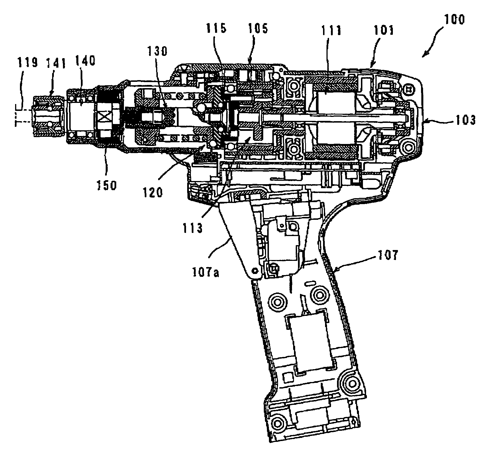
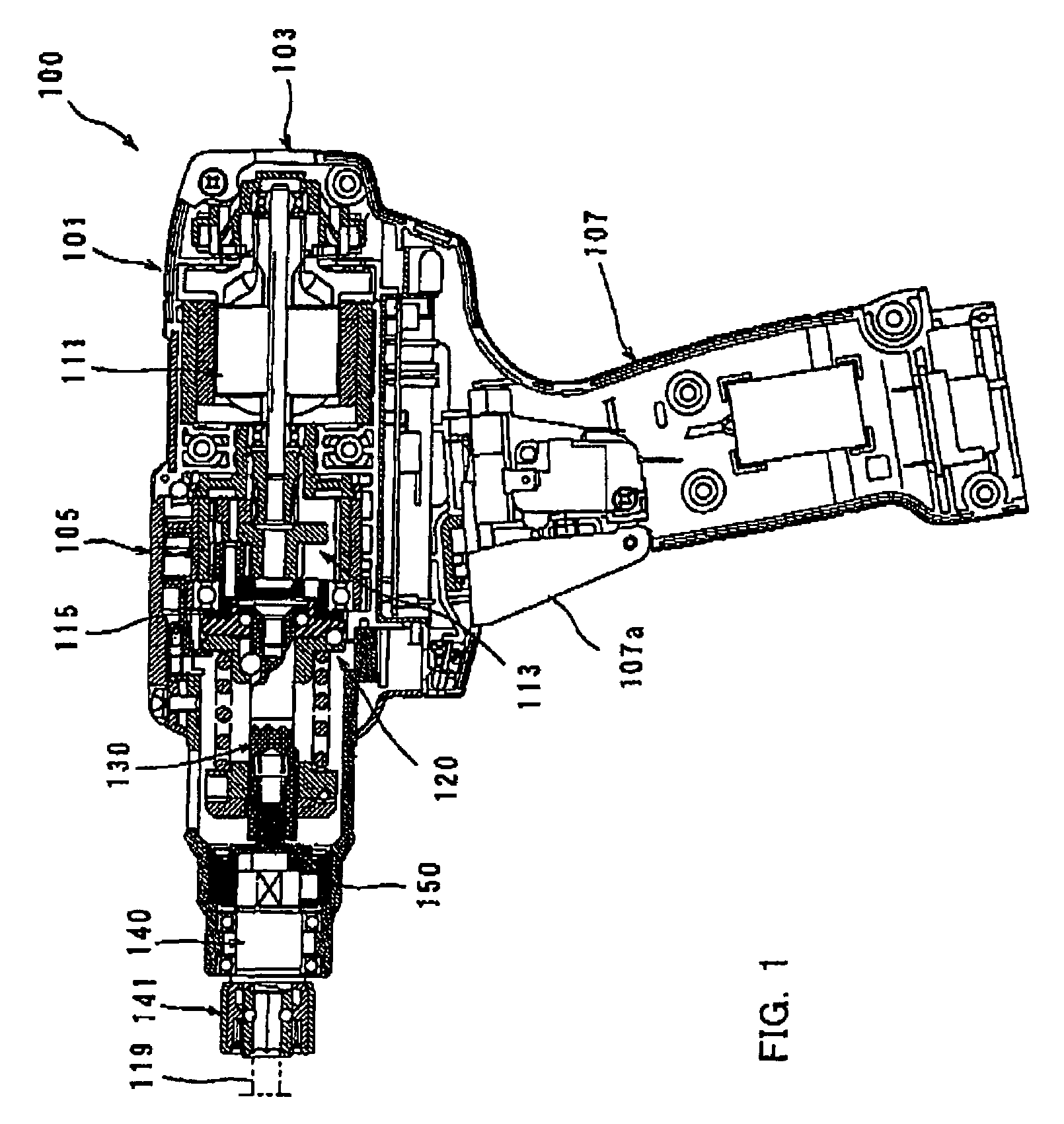
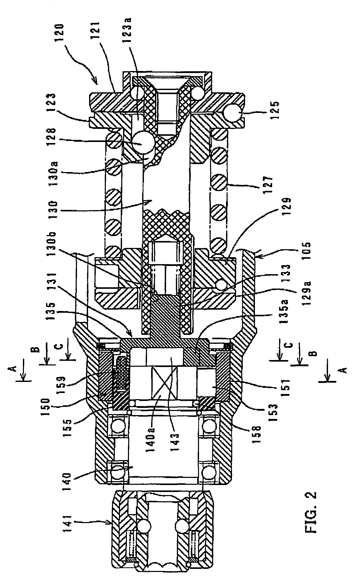
[0044]Each of the additional features and method steps disclosed above and below may be utilized separately or in conjunction with other features and method steps to provide and manufacture improved rotary fastening tools and method for using such rotary fastening tools and devices utilized therein. Representative examples of the present invention, which examples utilized many of these additional features and method steps in conjunction, will now be described in detail with reference to the drawings. This detailed description is merely intended to teach a person skilled in the art further details for practicing preferred aspects of the present teachings and is not intended to limit the scope of the invention. Only the claims define the scope of the claimed invention. Therefore, combinations of features and steps disclosed within the following detailed description may not be necessary to pace the invention in the broadest sense, and are instead taught merely to particularly describe ...


PUM


Abstract

It is an object of the invention to provide an effective technique for avoiding the influence of reaction during tightening operation in the rotary fastening tool. Representative rotary fastening tool includes a tool body, a motor housed within the tool body, a driving-side rotating member that is rotationally driven by the motor, a driven-side rotating member that is disposed coaxially with the driving-side rotating member, a tip-end side rotating member that is disposed coaxially with the driven-side rotating member and rotationally driven via the driven-side rotating member, the tip-end side rotating member driving a tool bit to perform a tightening operation and a rotation control mechanism that allows the tip-end side rotating member to rotate in the tightening direction during the tightening operation of the tool bit, wherein, when the tip-end side rotating member is fixed to a workpiece with the tool bit during the tightening operation and when torque transmission from the driving-side rotating member to the driven-side rotating member is interrupted, the rotation control mechanism locks the tip-end side rotating member and the tool body together against rotation with respect to each other to prevent the tool body from rotating in the tightening direction.

Description

BACKGROUND OF THE INVENTION[0001]1. Field of the Invention[0002]The present invention relates to a rotary fastening tool and typically to a rotary fastening tool with a torque limiter that interrupts torque transmission from the input side to the output side when torque acting on a tool bit reaches a set value.[0003]2. Description of the Related Art[0004]Japanese utility model publication No. 50-33759 discloses an electric screwdriver having a torque limiter that transits torque from the input side to the output side. In the known art, a pair of clutches for torque limiter is provided between the input side and the output side. The clutches have clutch teeth formed in the respective clutch surfaces facing with each other and engage with each other in the direction of rotation. One of the clutches is biased toward the other by a spring member. During screw-tightening operation, when the screw head is seated on the workpiece, torque acting upon the output side clutch increases. When t...

Claims


Application Information

Patent Timeline
Patent Type & Authority Patents(United States)
IPC IPC(8): B23B33/00
CPCB25B21/00B25B23/14B25F5/001B25B23/141Y10T82/26
Inventor TOKUNAGA, MANABU
Owner MAKITA CORP
Learn More