Sound absorbing structure of electronic equipment

a technology of electronic equipment and sound absorption, which is applied in the direction of liquid fuel engines, instruments, machines/engines, etc., can solve the problems of dispersion of cooling fluid distribution, obstacle to uniform cooling of the inside etc., and achieve the effect of reducing the noise maintaining the cooling capability of the electronic equipment, and increasing the attenuation of the sound

Inactive Publication Date: 2010-05-11
HITACHI LTD
View PDF13 Cites 38 Cited by
  • Summary
  • Abstract
  • Description
  • Claims
  • Application Information

AI Technical Summary

Benefits of technology

[0010]By installing the sound absorbing structure of the present invention in an air intake and discharge direction inside or outside a case of the electronic equipment equipped with the blower, it is possible to reduce the noise of the electronic equipment while maintaining the cooling capability of the electronic equipment. Further, by changing the installation place, the number or the angle of basic sound absorbing members of the sound absorbing structure, it becomes possible to cope with the change in size of the rack cabinet, and the change in required cooling capability across several generations of the CPU inside the electronic equipment.
[0011]Moreover, since the penetrating opening is a passing opening of the cooling fluid and at the same time is a space where the sound collides to be absorbed, if the area of the penetrating plane is the same, the attenuation of the sound becomes larger as the length of the channel becomes long. Accordingly, since the sound absorbing structure of the present invention comprises a large number of penetrating openings which becomes inclined or curved long sound absorbing channels, the volume necessary for the sound absorbing structure can be made compact. Moreover, since the distribution of the cooling fluid before and behind the penetrating openings and the pressure loss generated when the cooling fluid passes can be made uniform by arranging the position and the size of the penetrating opening so as to be in a well-balanced state, the sound absorbing structure of the present invention does not disturb the cooling capability.

Problems solved by technology

In addition, there has been the danger that the imbalanced sound absorbing structure in which the plurality of acoustic materials are combined causes dispersion of the distribution of cooling fluid and the pressure loss caused when the cooling fluid passes, which may be an obstacle to uniform cooling of the inside of the electronic equipment.

Method used


Image

  • Sound absorbing structure of electronic equipment
  • Sound absorbing structure of electronic equipment
  • Sound absorbing structure of electronic equipment

Examples


second embodiment

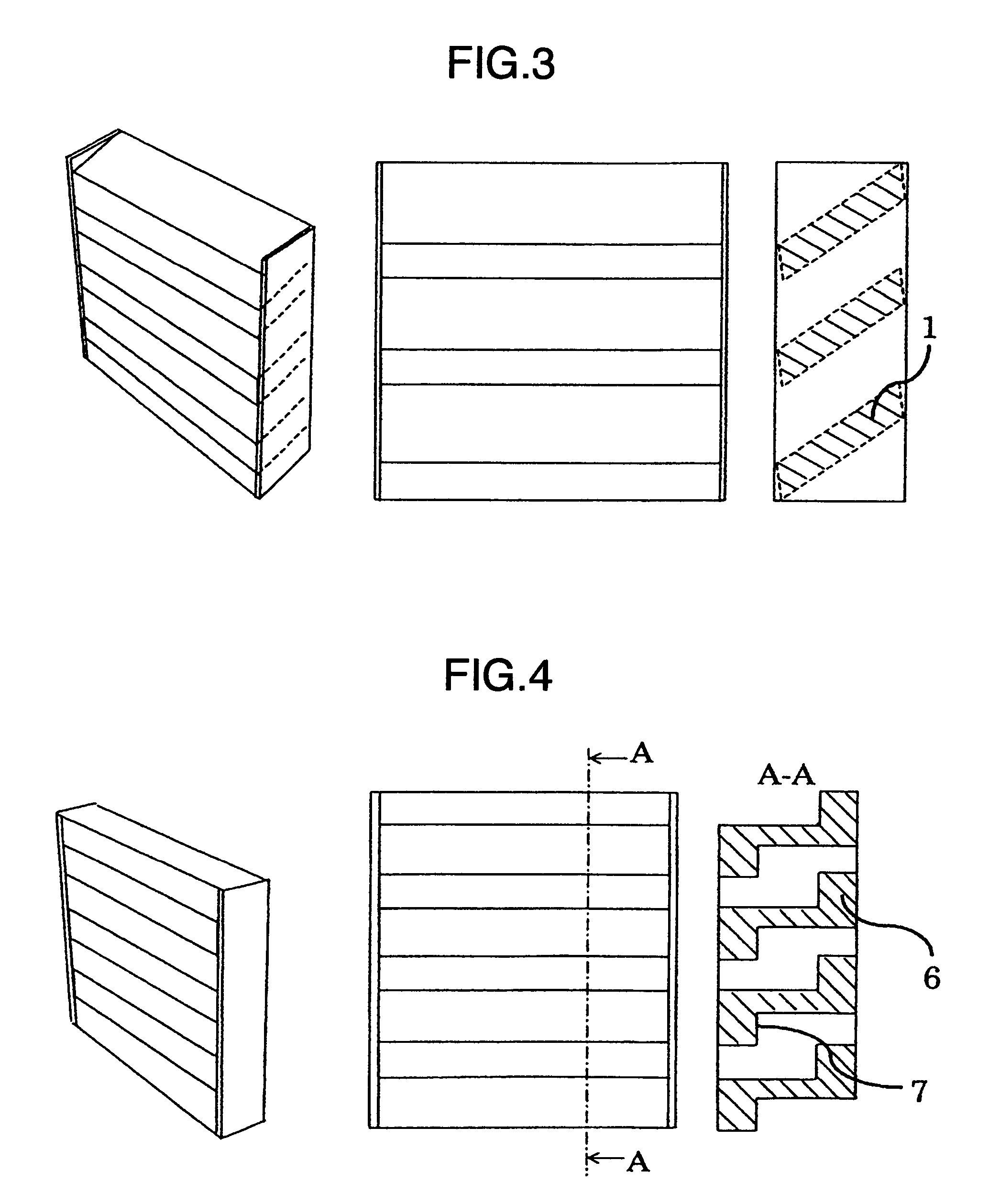
[0025]FIG. 3 shows the present invention. The composition basic members of this embodiment are quite the same as FIG. 1. However, the number of the basic sound absorbing members 1, the connecting point with the plate material 4, and the inclination with respect to the plate material 4 are changed, and thereby it is possible to change not only the sound absorbing effect but also the fluid resistance.

third embodiment

[0026]FIG. 4 shows the present invention. The basic composition member in this embodiment is an acoustic material in which a curved channel is provided in the penetrating opening so that the noise source cannot be seen when the penetrating plane is viewed from the front. The sound vertically incident on the penetrating plane collides against a wall surface 7 consisting of a curved basic member 6, and is absorbed.

fourth embodiment

[0027]FIG. 5 shows the present invention. The basic composition member in this embodiment is an acoustic material in which a V-shaped channel is provided in the penetrating opening so that the noise source cannot be seen even when the penetrating plane is viewed from any direction. The sound incident on the penetrating plane collides against a wall surface 9 consisting of a V-shaped basic sound absorbing member 8, and is absorbed.


PUM


Abstract

In order to provide sound absorbing structure capable of reducing the noise of electronic equipment while maintaining the cooling capability of the electronic equipment, there is provided sound absorbing structure in which a plurality of penetrating openings are provided by arranging a plurality of acoustic materials having a predetermined shape at predetermined intervals in a flow channel of cooling fluid from a blower, and the plurality of acoustic materials are arranged so that the sound vertically incident on a penetrating plane of the penetrating openings from the blower does not directly go out of the electronic equipment.

Description

CROSS-REFERENCE TO RELATED APPLICATION[0001]The present application claims priority from Japanese application JP 2007-069756 filed on Mar. 19, 2007, the content of which is hereby incorporated by reference into this application.BACKGROUND OF THE INVENTION[0002]1. Field of the Invention[0003]The present invention relates to sound absorbing structure of electronic equipment having the structure for cooling a heat generating element by means of a blower.[0004]2. Description of Related Art[0005]It is common knowledge that the development of a semiconductor used for electronic equipment, especially of a semiconductor as typified by a CPU of information processing equipment is remarkable, and the semiconductor heads for high heat generating amount and high density. In this connection, due to increase of the mounting number of blowers for cooling and the revolution speed of the blower, the noise value of the equipment also tends to increase. On the other hand, the frequency of placing the ...

Claims


Application Information

Patent Timeline
Patent Type & Authority Patents(United States)
IPC IPC(8): F01N13/00E04B1/82G10K11/00H02K5/24H05K7/20G10K11/04E04F17/04
CPCG06F1/182F24F13/24
Inventor GOTO, AKIRAIDEL, AKIOTSUBAKI, SHIGEYASU
Owner HITACHI LTD
Why Eureka
Try Eureka