Optical switch

a technology of optical switches and switches, applied in the field of optical switches, can solve problems such as explosion hazards, increase the complexity and cost of such systems, and present electrical shock risks

Active Publication Date: 2010-05-11
COX CHRISTOPHER E
View PDF20 Cites 12 Cited by
  • Summary
  • Abstract
  • Description
  • Claims
  • Application Information

AI Technical Summary

Problems solved by technology

Many working environments present explosion hazards or present a risk of electrical shock.
One hazardous environment is a pumping station or a tank that contains hazardous and / or flammable or volatile gases or liquids and chemicals to be pumped.
These all present a spark hazard, and if a breakdown in insulation occurs along the electrical path, an explosion can result.
This technique is not generally used to remotely signal a device, such as a signal to engage / disengage a pump (such as a dosing pump) at discrete levels, as these level detectors will detect all fluid levels requiring additional logic circuits to select a predetermined height or level for operation of a pump, thereby raising the complexity and expense of such as system.
In some hazardous environments, explosion proof containers are used to contain equipment or devices that may present a possible sparking hazard, such as controls, pumps, motors, etc.
Hence, when an operator is onsite, the operator cannot manually activate / deactivate the device within the hazardous area unless the activation device is in an explosion proof housing.

Method used


Image

  • Optical switch
  • Optical switch
  • Optical switch

Examples


Embodiment Construction

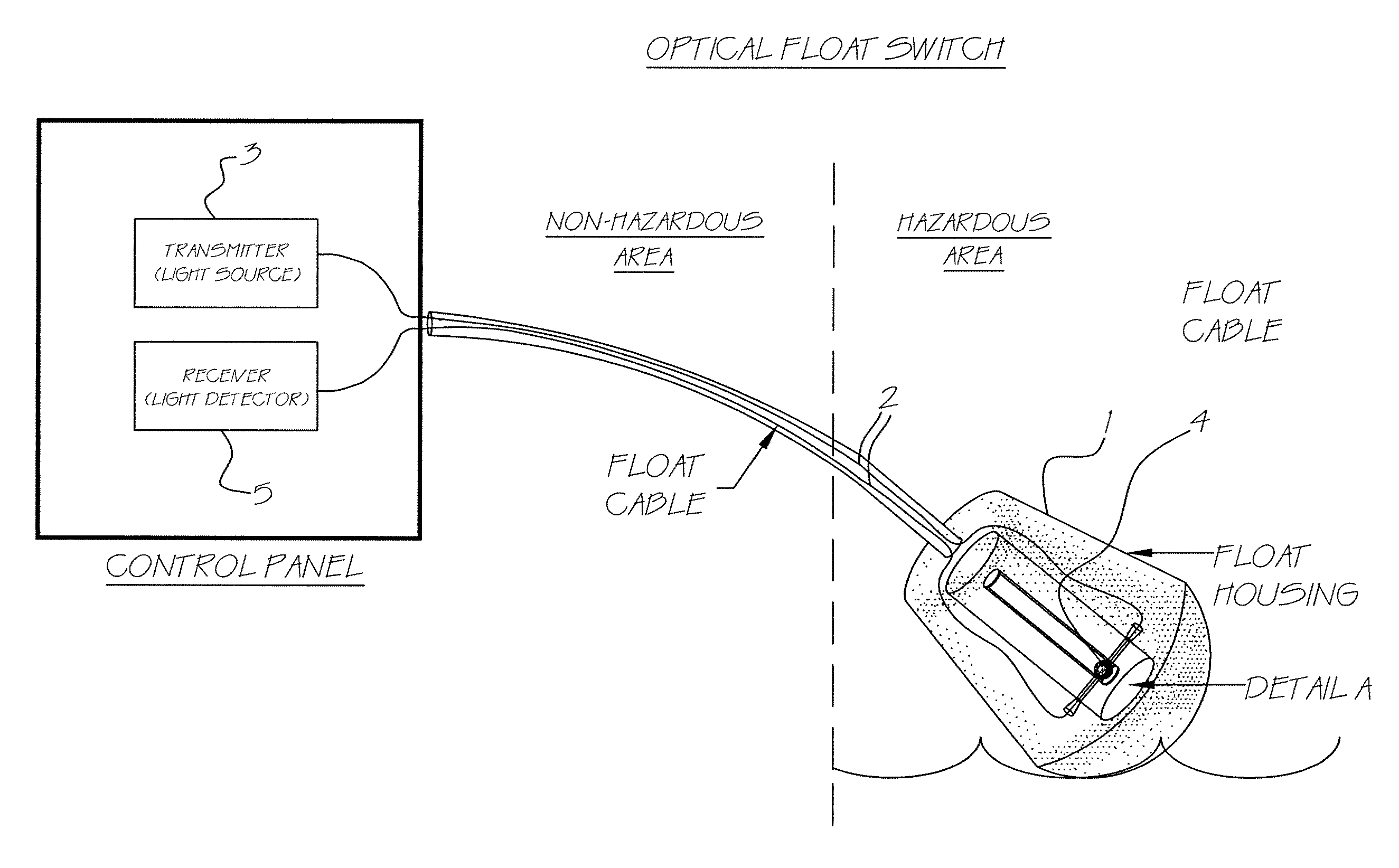
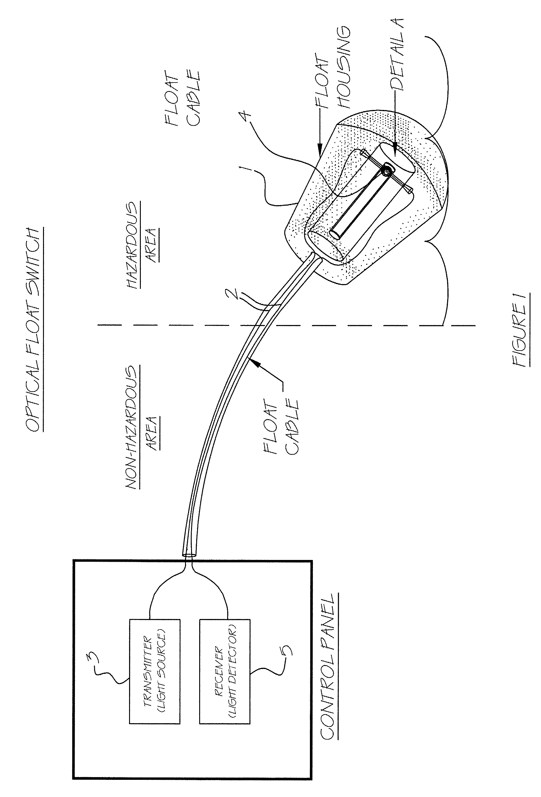
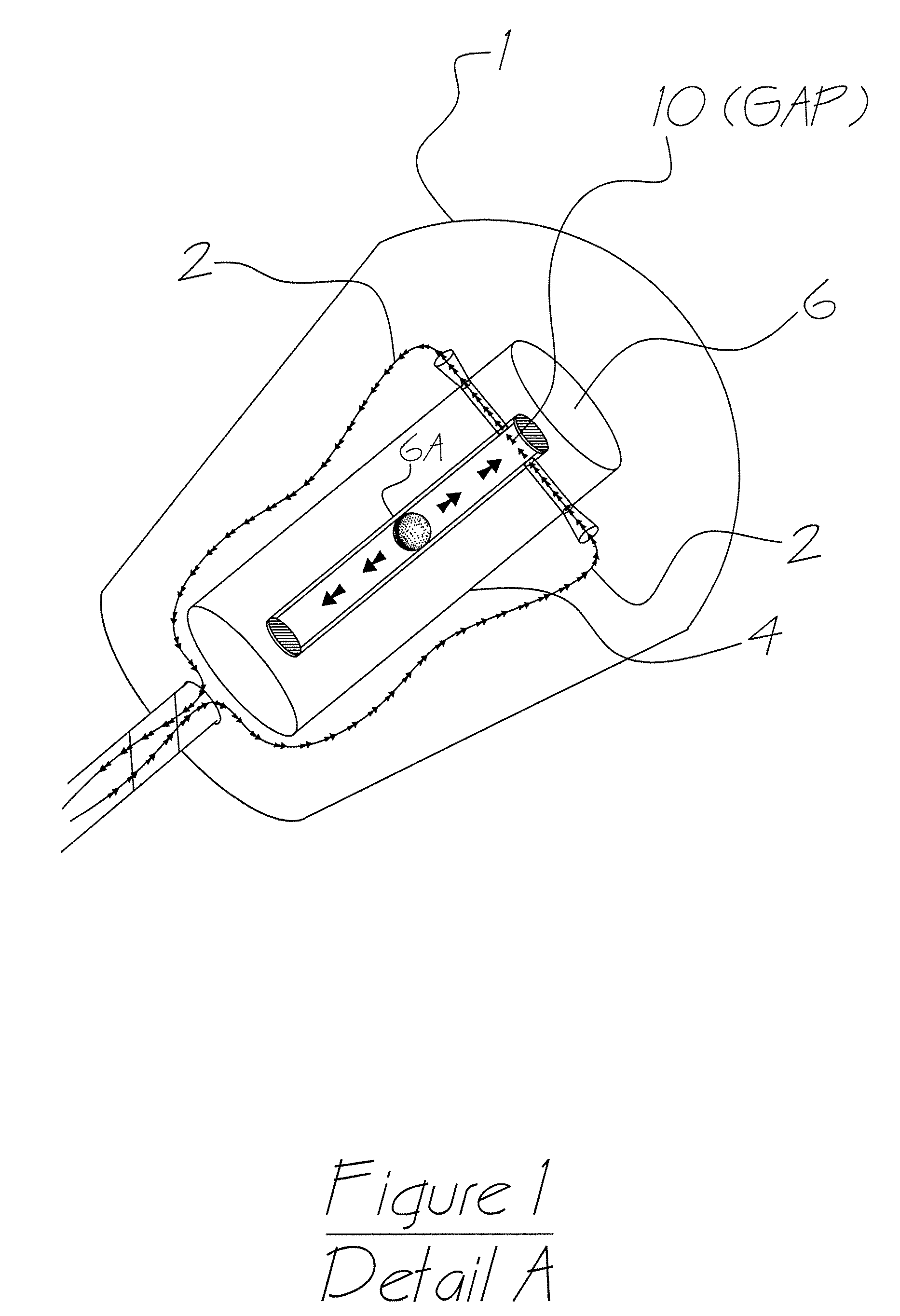
[0025]Shown in FIG. 1 is an embodiment of the invention in a float. The invention includes a housing 1, two light guides 2 (hereafter described as fiber optic cables), a light source 3, and a means to interrupt or modify the alignment, here by interposing an object between the distal ends. The housing shown has an interior section. The two cables 2 are positioned into the housing 1. Each cable terminates at or within the floating housing 1. The terminal (or distal) ends of the cables are positioned in the housing near each other, but separated by a gap 10 (see FIG. 1, detail A). The gap 10 is generally positioned in the separator assembly 6 within the housing 1. The separator assembly fixes the relationship of the cable terminal ends and maintains the gap, although this relationship can be fixed through use of the housing alone. The gap can vary in size, with 0.01-0.5 inch suitable for most applications, but could be larger. Some light detectors can sense the presence of light radia...


PUM


Abstract

An optical switch having a housing, a light source and a light detector. The light source and light detector are located remote from the housing, The light source is connected to the housing with a first light guide, and the light detector is connected to the housing with a second light guide. The first and second light guide cables have distal ends positioned through the housing and are optically aligned but separated by a gap. The switch includes a device to interrupt a light beam that is usually adapted to removably occupy the gap. The switch may be embodied in a float.

Description

FIELD OF INVENTION[0001]The invention relates to switches used primarily in hazardous environments, such as switches used in liquid level detection in tanks or switches to activate equipment within a hazardous environment.BACKGROUND OF THE INVENTION[0002]Many working environments present explosion hazards or present a risk of electrical shock. One hazardous environment is a pumping station or a tank that contains hazardous and / or flammable or volatile gases or liquids and chemicals to be pumped. Float switches are commonly used in applications of this sort to detect level for activation of a pump (see FIG. 2), but float switches generally have electrical current that passes through wires and a switch housed within the float, such as a mercury switch located in the float. Wires from the float switch run to a control panel (or other device) located external to the tank or pit and are located outside the hazardous area. Some specialty control panels are explosion proof and can be locat...

Claims


Application Information

Patent Timeline
Patent Type & Authority Patents(United States)
IPC IPC(8): G08B21/00
CPCG01F23/0038G01F23/2921G01F23/76G01F23/30Y10S250/901
Inventor COX, RALEIGH I.COX, CHRISTOPHER E.
Owner COX CHRISTOPHER E
Why Eureka
Try Eureka