
Single-piece part for making a cable anchoring jaw and method for making such a jaw

Inactive Publication Date: 2010-05-18
FREYSSINET INT STUP
View PDF3 Cites 11 Cited by
  • Summary
  • Abstract
  • Description
  • Claims
  • Application Information

AI Technical Summary

Benefits of technology

[0014]An object the present invention is to improve jaws of the type described in French patent 2 586 076 by reducing the impact of the above-mentioned problems.
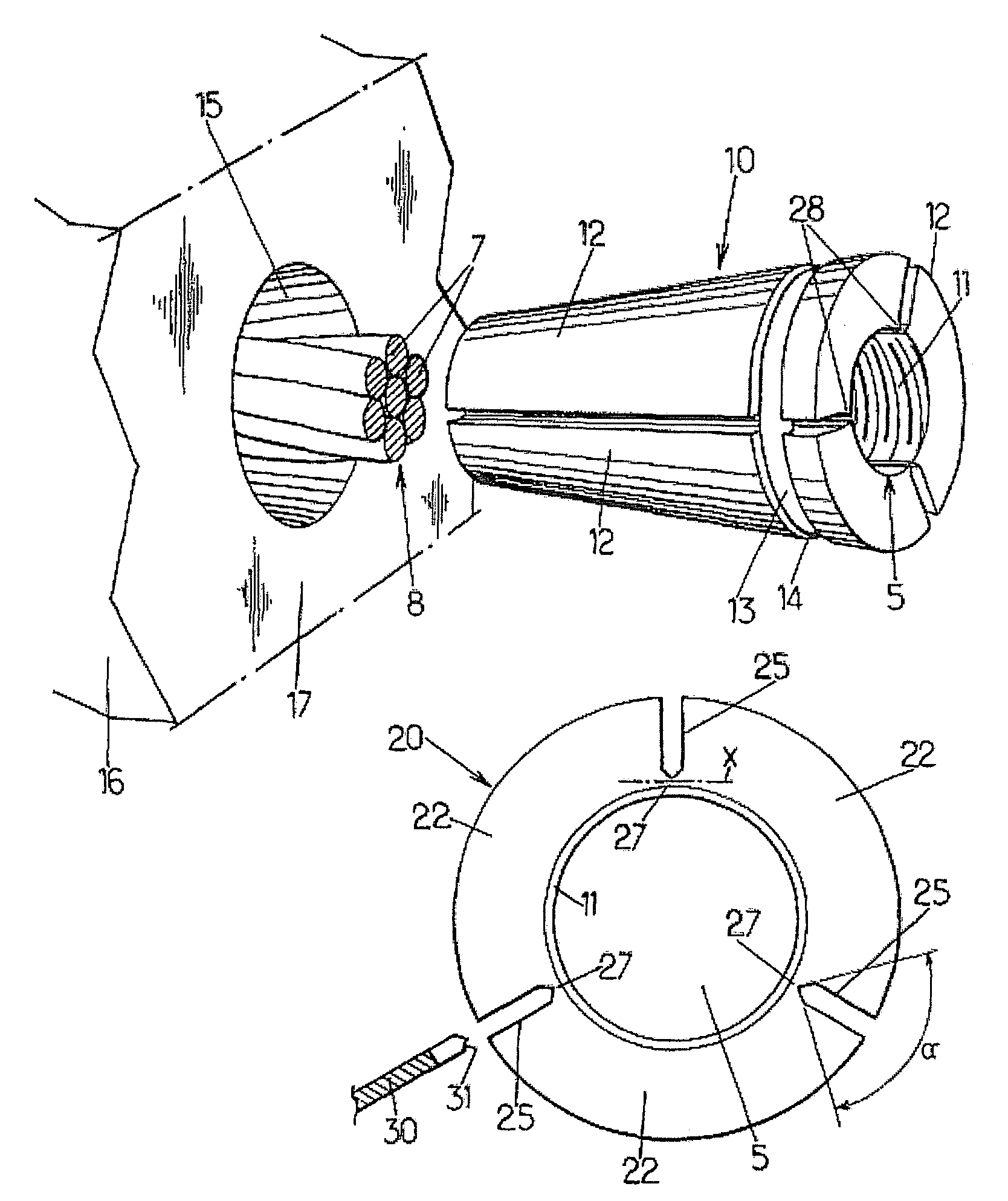
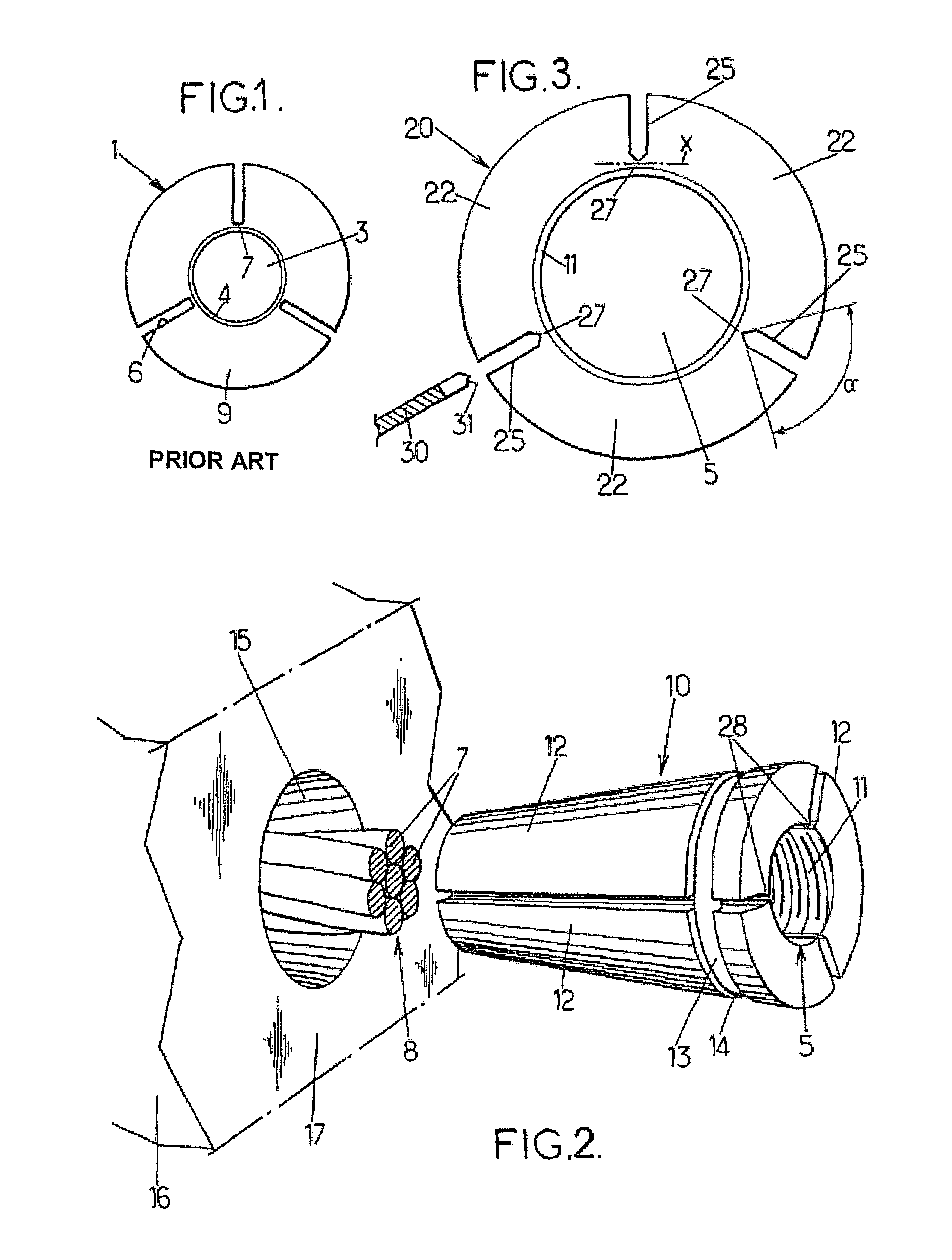
[0017]As a result, the clamping forces are better distributed on the periphery of the component across the clamping surface within the bridge.
[0018]The ledges which the broken bridges leave on the radial faces of the wedges at the edge of the cylindrical bore of the jaw are of a well-determined shape and they can assist in transmitting the forces to the tendon. By thus making use of the entire width of the angular segment, the distribution of forces is also improved (peak pressures are reduced).
[0019]Furthermore, these ledges virtually eliminate the problems explained above relating to excessive widening of one of the spaces between wedges.
[0020]In one advantageous embodiment, the surface that each bridge presents towards its respective slot is substantially V-shaped. The inclination of the faces of the V therefore allows the clamping forces to be transmitted across the entire surface of the striations generally present on the wall of the cylindrical bore, which significantly increases the uniformity of the clamping action on each of the wires making up the anchored tendon or strand. The inclination of the faces of the V also enables the wedge segments to be positioned so as to be regularly spaced by the normal radial sliding action of the wedge segment on the parts of the V.

Problems solved by technology

A problem encountered with jaws of this type is that the bridge rupturing is not well controlled.
These problems can be detrimental to the quality of the anchoring.
If a piece of bridge remains on the radial face of a wedge at only certain points of the jaw length, this may cause the cylindrical bore to deform because of the imperfect contact bearing between adjacent wedges, which will affect the uniformity of the clamping action.
Pieces of bridge may also be deformed or separated from the wedge under the effect of the stress applied during the anchoring process, in which case these pieces are likely to come in an undesirable manner between the wedges, between the wedges and the tendon or between the wedges and the frusto-conical orifice of the anchoring block.
This would also lead to ineffective clamping of the tendon, which may cause slipping.
In the typical situation where N=3 and where the cuts leave spaces of 1.5 mm between the wedges, one could end up with one space of 4.5 mm, which would be seriously detrimental to the anchoring of a conventional seven-wire strand whose peripheral wires have a diameter of 5 mm.
The fact that rupturing of the bridges is not very well controlled does not permit to eliminate this disadvantage of the conventional jaws.

Method used


Image

  • Single-piece part for making a cable anchoring jaw and method for making such a jaw
  • Single-piece part for making a cable anchoring jaw and method for making such a jaw

Examples


Embodiment Construction

[0031]FIG. 2 illustrates the shape of an anchoring jaw 10 according to the invention, used to clamp a cable tendon 8 such as, e.g., a pre-stressing or stay cable strand. This exemplary jaw 10 has a generally frusto-conical shape with a central cylindrical bore 5, through which the strand 8 will be inserted, the internal wall of the bore having transverse striations 11 to provide a tight grip on the strand. This frusto-conical shape is divided into three angular segments of 120 degrees, formed by three identical wedges 12. These wedges 12 are assembled by means of an ring 13 located in a circumferential groove 14 close to the widest end of the jaw.

[0032]This jaw 10 engages a matching frusto-conical orifice 15 provided in an anchoring block 16. The procedure for anchoring a strand is as follows: the strand 8 is threaded through the orifice 15; the jaw 10 is placed around this strand; traction is applied to the strand at the part projecting beyond the external face 17 of the anchoring ...


PUM

PropertyMeasurementUnit
Thicknessaaaaaaaaaa

Abstract

The invention concerns a single-piece part for producing a cable anchoring jaw. The single-piece part includes several angular portions arranged about a generally cylindrical duct, assembled by clamps adjacent to the duct. Each clamp is located at the bottom of one particular radial slot extending between two portions from the part periphery. Each clamp has towards its own particular slot a surface whereof a part at least is inclined relative to the direction perpendicular to the slot radial plane, such that the clamp radial thickness has a minimum in a specific position along the direction, thereby ensuring the position where the clamp will be broken to obtain the jaw wedges from the part portions, which enables to better control for clamping the cable strand in the jaw.

Description

TECHNICAL FIELD OF THE INVENTION[0001]The present invention relates to the jaws used to anchor cables on anchoring blocks such as pre-stressing cables used in civil engineering applications, bridge stay cables,DESCRIPTION OF THE RELATED ART[0002]These jaws are usually of a frusto-conical shape, and they have an axial bore of a generally cylindrical shape which receives the cable tendon to be anchored. They co-operate with seats having at least one matching frusto-conical portion, those seats being cut through the anchoring blocks, with the cable tendons to be anchored extending therethrough.[0003]The jaws in question consist of several (usually two, three or four) identical elements—that will be referred to as “wedges” hereafter—coming from an original component, delimited on the outside by a frusto-conical surface and having a cylindrical axial bore extending therethrough, the internal face of which is advantageously striated. The original component is divided into wedges by making...

Claims


Application Information

Patent Timeline
IPC IPC(8): B23P17/00F16G11/04E04C5/12
CPCE04C5/122F16G11/04Y10T24/3909Y10T24/3907Y10T29/49792Y10T29/4979F16G11/106
Inventor PERCHERON, JEAN-CLAUDEPELTIER, MANUEL
Owner FREYSSINET INT STUP
Learn More