Integrated plant cooling system

a technology of integrated power plant and cooling system, which is applied in the direction of efficient propulsion technology, machines/engines, light and heating apparatus, etc., can solve the problems of penalizing the efficiency and cost of over all power plant, causing the exchanger to have a higher area, etc., and achieves the effect of effective and efficient cooling packag

Inactive Publication Date: 2010-05-18
GENERAL ELECTRIC CO
View PDF23 Cites 18 Cited by
  • Summary
  • Abstract
  • Description
  • Claims
  • Application Information

AI Technical Summary

Benefits of technology

[0021]The following embodiments of the present invention have many advantages, including providing a cost effective method of integrating the independent power plant cooling skids into one single cooling system utilizing an absorption or a mechanical chiller providing a cooling medium for all power plant equipment requiring cooling, where the controlled lower temperature cooling medium will result in significant savings, simplify the plant operation and provide a reliable source of cooling medium.

Problems solved by technology

This high temperature cooling fluid (air and water at ambient) causes the heat exchangers to have higher area and penalizes the over all power plant efficiency and cost.

Method used


Image

  • Integrated plant cooling system
  • Integrated plant cooling system
  • Integrated plant cooling system

Examples


second embodiment

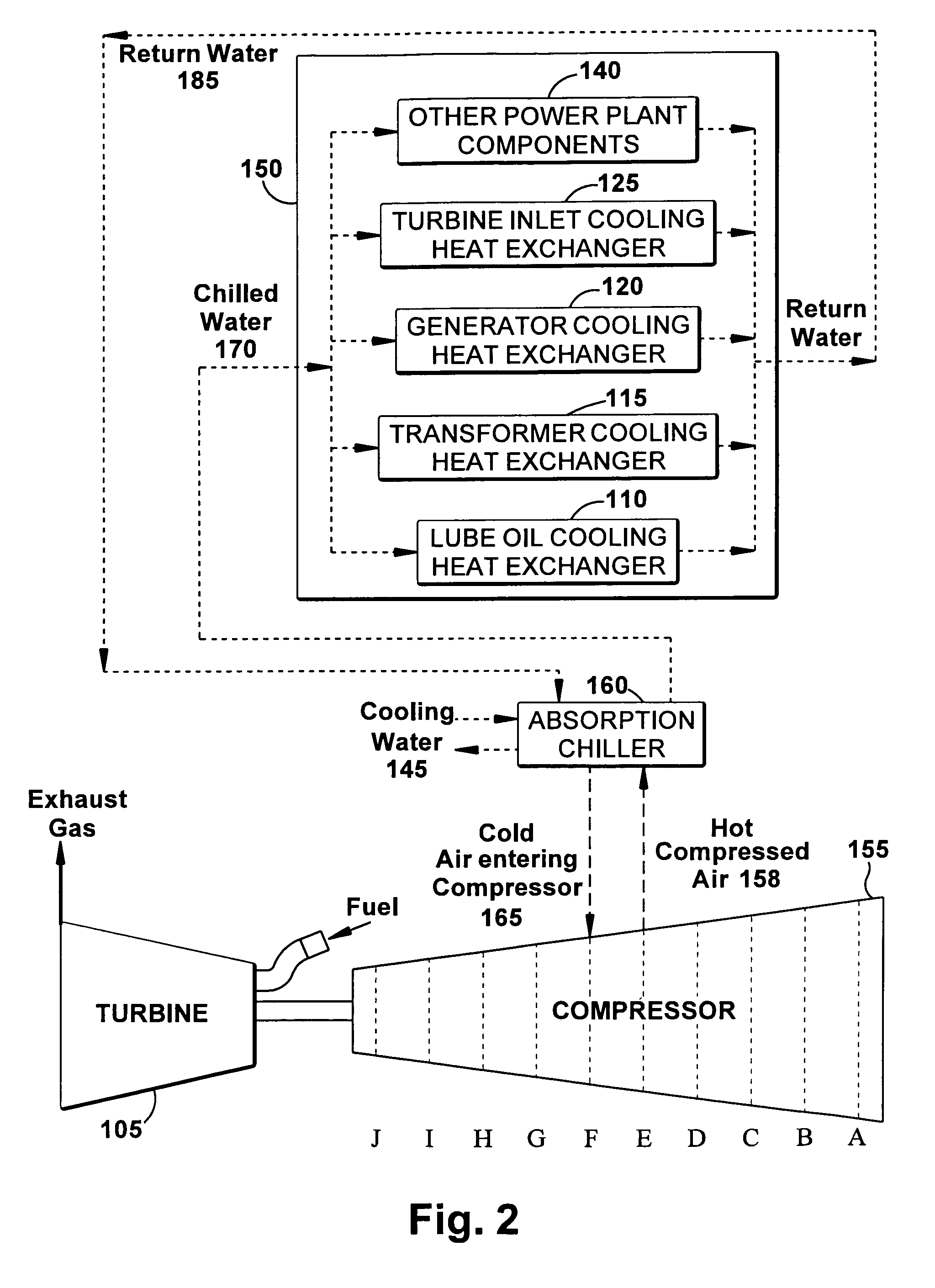
[0028]FIG. 3 illustrates the present invention providing an absorption chiller, powered by hot compressed interstage air from the air compressor, and a first intercooler supplying an integrated cooling skid for power plant components. The integrated cooling skid 250 may include a lube oil cooling heat exchanger 210, a transformer cooling heat exchanger 215, a generator cooling heat exchanger, 220, a turbine inlet cooling heat exchanger 225 and other heat exchangers for miscellaneous power plant components requiring cooling 240.

[0029]Hot compressed air 258 is extracted from an interstage D of compressor 255 and ducted to absorption chiller 260 to provide a heating fluid for ALC cooling of the cooling medium. The cooling medium, chilled water 270 is circulated to the integrated cooling skid 250. Returning cool air 265 from absorption chiller 260 is ducted through a first intercooler 275 to further lower temperature of cold return air 280 to interstage E of compressor 255, thereby prov...

embodiment 2

[0030]A further alternative within Embodiment 2 is that intercooling can be provided by a cooling water supply 247 when the demand on absorption chiller is high due to high cooling requirements from other power plant equipment.

third embodiment

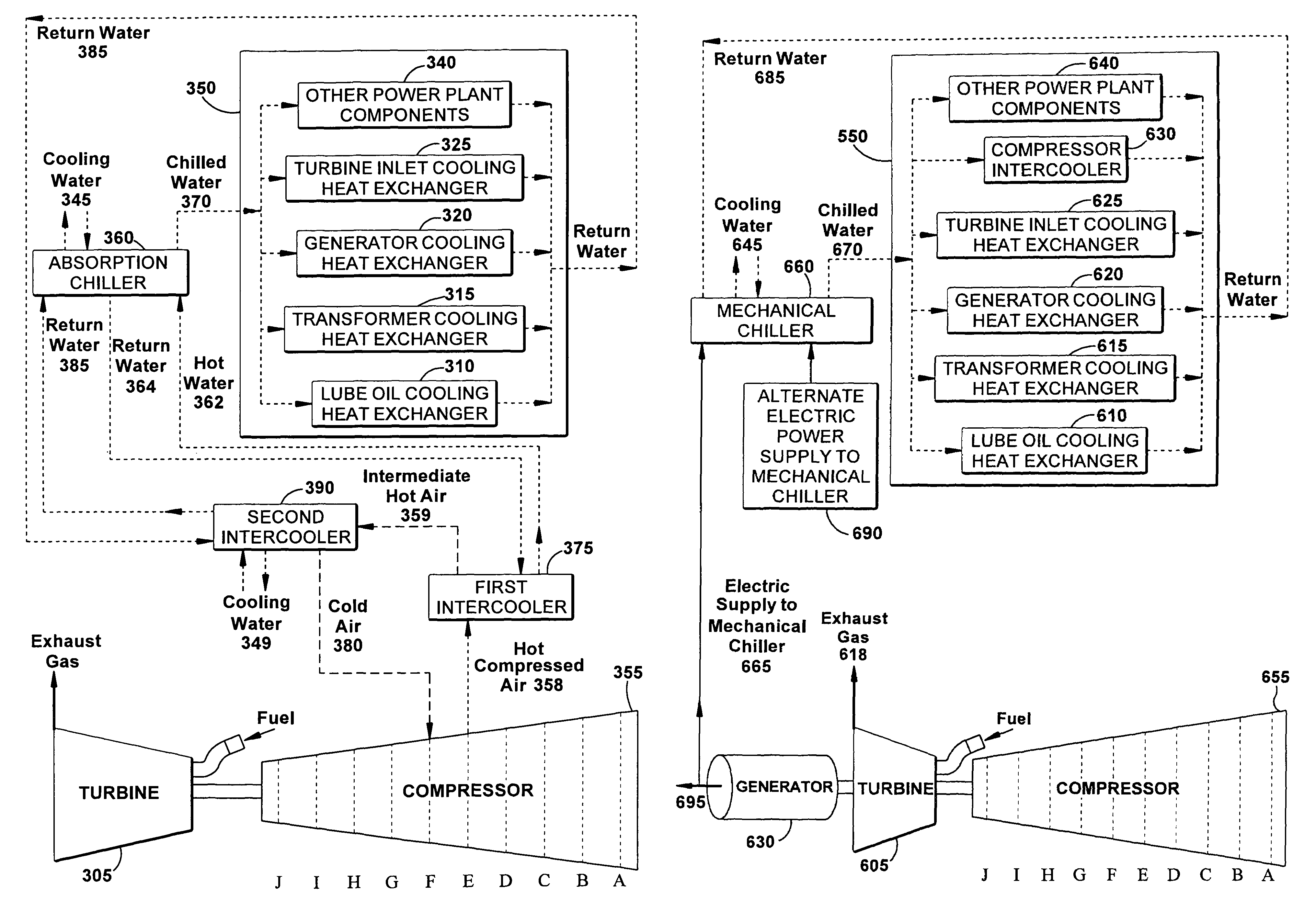
[0031]FIG. 4 illustrates the present invention providing an absorption chiller, powered by hot interstage air from the air compressor, a first intercooler and a second intercooler supplying an integrated cooling skid for power plant equipment. The integrated cooling skid 350 may include a lube oil cooling heat exchanger 310, a transformer cooling heat exchanger 315, a generator cooling heat exchanger, 320, a turbine inlet cooling heat exchanger 325 and other heat exchangers for miscellaneous power plant components requiring cooling 340.


PUM


Abstract

An integrated power plant cooling system for an electrical generating power plant driven by a gas turbine to cool power plant components is provided. The integrated cooling system includes a heat source extracted from the power plant and an absorption chiller utilizing energy from the heat source to cool a chilling medium. An integrated cooling skid includes heat removal devices for a plurality of power plant components. The chilling medium output from the absorption chiller is circulated to the heat removal devices for the power plant components of the integrated cooling skid. Plant cooling water may remove heat from the absorption chiller.

Description

BACKGROUND OF THE INVENTION[0001]This invention relates to a power plant cooling system for power plant equipment and more specifically to an integrated power plant cooling system utilizing multiple methods for generating a cooling medium to remove heat from an integrated skid of power plant cooling components. Typical cooling requirements of a power plant include generator cooling; lube oil cooling; transformer cooling; turbine inlet cooling; turbine inlet air cooling and intercooler cooling; and cooling for other miscellaneous components.[0002]Many power plant components such as generators, lube oil systems, and transformers, require cooling to reject the heat generated by inefficiencies (windage, bearings, electrical heating, etc.), while additional cooling functions directly impact plant performance, as for example turbine inlet air cooling, compressor inlet air cooling or compressor intercooling. Individual cooling devices for these components typically utilize air or water-coo...

Claims


Application Information

Patent Timeline
Patent Type & Authority Patents(United States)
IPC IPC(8): F02C1/00F02G3/00
CPCF01D25/12F01K17/005F01K23/10F02C7/12F02C7/143F05D2230/50Y02E20/16Y02T50/675F05D2230/60Y02T50/60F25B11/00F02C7/00
Inventor CHILLAR, RAHUL J.SMITH, RAUB W.
Owner GENERAL ELECTRIC CO
Why Eureka
Try Eureka