Motorcycle

a motorcycle and gear technology, applied in the field of motorcycles, can solve the problems of low productivity of the main line, achieve the effects of facilitating a favorable work posture, and reducing the assembling time of the torque rod

Active Publication Date: 2010-05-18
HONDA MOTOR CO LTD
View PDF13 Cites 4 Cited by
  • Summary
  • Abstract
  • Description
  • Claims
  • Application Information

AI Technical Summary

Benefits of technology

[0014]In the first aspect of the present invention, an end of the torque rod is assembled to the rear fork. Accordingly, the rear wheel, the gear case, and the torque rod can be assembled to the rear fork all at once, and thus, the assembling of the torque rod to the rear fork can be done in advance in the sub line. The torque rod does not have to be assembled to the rear fork in the main line, which results in a higher productivity of the main line.
[0015]In addition, the assembling work of the torque rod to the rear fork done in the sub line facilitates a favorable work posture, and thus requires a shorter assembling time of the torque rod.
[0016]In the second aspect of the present invention, the torque rod is joined either to the rear fork or to the gear case, with the elastic member placed in between. Accordingly, the elastic member can absorb a shock that derives from the fluctuation of the torque transmitted through the power train. Now that the elastic member can absorb the shock that derives from the fluctuation of the transmitted torque, another buffering system provided in another portion against the shock, such as a damper member provided in the gear case, can be made smaller in size, or such a buffering system in another portion can be eliminated altogether.
[0017]In the third aspect of the present invention, the three positions—the meshing position of the gear of the drive-shaft side with the final driven gear, the joining position of the torque rod to the gear case, and the position of the bearing supporting the final driven gear—are arranged in the same vertical plane. Accordingly, force acting on the meshing position is less likely to produce a torsion moment in the gear case.
[0018]Since the torsion moment is less likely to generate in the gear case, the gear case needs less strength than in the case where the meshing position, the joining position, and the position of bearing are not arranged in the same vertical plane. Since the gear case needs less strength, it can be made in a smaller wall thickness, and thus can be made lighter in weight.

Problems solved by technology

As a result, the more time the assembling work of the torque rod 32 takes, the lower the productivity of the main line becomes.

Method used


Image

  • Motorcycle
  • Motorcycle
  • Motorcycle

Examples


Embodiment Construction

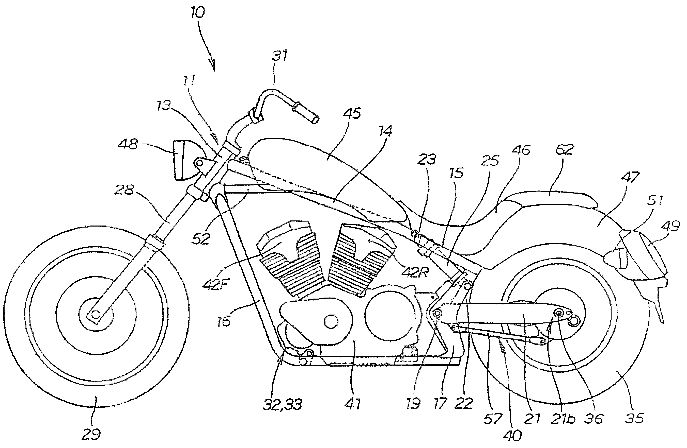
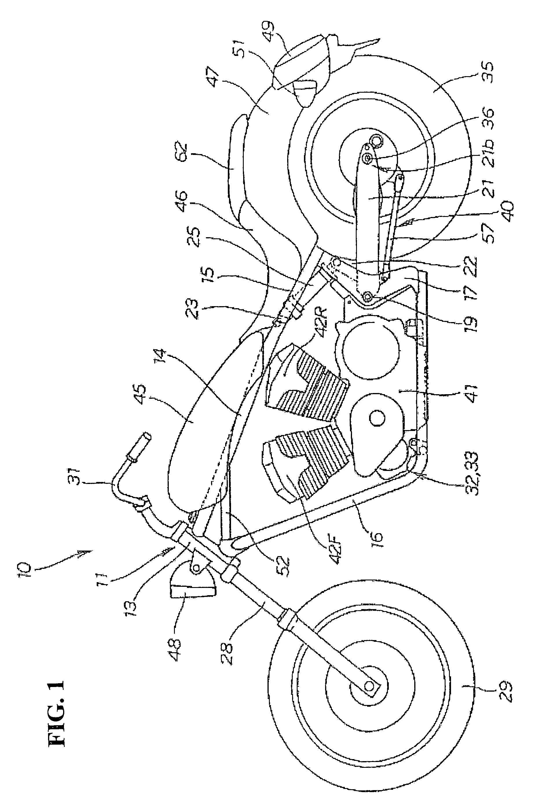
[0027]FIG. 1 is a left side view of a motorcycle according to the present invention.

[0028]A motorcycle 10 is a vehicle provided with a body frame 11. The body frame 11 is configured as follows. A head pipe 13 is provided in the front end portion of the vehicle, and a main frame 14 extends rearward from the head pipe 13. Seat rails 15, 15 (only the seat rail 15 of the near side is shown in the drawing) extend rearward from the rear end portion of the main frame 14, and down frames 16, 16 (only the down frame 16 of the near side is shown in the drawing) extend obliquely downward from the head pipe 13. Rear frames 17, 17 (only the rear frame 17 of the near side is shown in the drawing) are also provided. Each rear frame 17 links the rear end of each of the down frames 16, 16 with the rear end of the corresponding one of the seat rails 15, 15. A pivot shaft 19 is attached to the rear frames 17, 17 so as to pivot freely, and a rear fork 21 is attached to the pivot shaft so as to swing up...


PUM


Abstract

A motorcycle is provided with a rear fork attached to a body frame so as to swing up and down freely. A rear wheel is attached to the rear end portion of the rear fork, a gear case is attached to a side of the rear wheel, and a drive shaft is provided between the gear case and an output shaft of a power unit. The output of the power unit is transmitted to the rear wheel via the drive shaft and the gear case. In the motorcycle, the gear case is supported by a rear-wheel axle provided in the rear end portion of the rear fork. A torque rod, which links an outer periphery portion of the gear case with the rear fork, serves as a stopper for rotation of the gear case. The resulting configuration provides a shaft-drive system that reduces the assembling time of the torque rod, and improves the productivity of the main line.

Description

CROSS-REFERENCE TO RELATED APPLICATION[0001]The present application claims priority under 35 U.S.C. §119 to Japanese Patent Application No. 2006-254862, filed Sep. 20, 2006, the entire contents of which are hereby incorporated by reference.BACKGROUND OF THE INVENTION[0002]1. Field of the Invention[0003]The present invention relates to a motorcycle equipped with a shaft-drive system for transmitting the output of a power unit to a rear wheel.[0004]2. Description of Background Art[0005]A motorcycle equipped with a shaft-drive system for transmitting the output of a power unit to a rear wheel via a drive shaft and a gear case is known by the disclosure of, for example, Japanese Unexamined Patent Application Publication No. Sho 62-43388 (FIG. 1 and FIG. 2).[0006]A motorcycle 1 shown in FIG. 1 and FIG. 2 of the above-mentioned document (the reference numerals used in this and the next paragraphs are of the cited document) is a vehicle that includes: a frame 2; a rear fork 10 attached to ...

Claims


Application Information

Patent Timeline
Patent Type & Authority Patents(United States)
IPC IPC(8): B62K11/02
CPCB62M17/00B62K25/283B62K11/00B62K11/04
Inventor ITO, SHINJIIWAI, TOSHIYUKIICHIKAWA, TOSHIHIKO
Owner HONDA MOTOR CO LTD
Why Eureka
Try Eureka