Junction bolt, junction element, and electrically conductive coupling device

a junction element and coupling device technology, applied in the direction of threaded fasteners, connection contact parts, connection device connections, etc., can solve the problems of time-consuming placement and tightening of the cap nuts, and achieve the effect of simple and rapid assembly

Inactive Publication Date: 2010-05-18
NEWFREY
View PDF11 Cites 2 Cited by
  • Summary
  • Abstract
  • Description
  • Claims
  • Application Information

AI Technical Summary

Benefits of technology

[0004]An object of the invention is to create a junction bolt of the kind initially specified, and a junction element cooperating therewith as well as a coupling means derived therefrom, rendering possible simple and rapid assembly.
[0006]The conformation of the junction bolt according to an aspect of the invention has the advantage that the removal of a protective cap or cap nut may be dispensed with. Instead, the protective shaft at assembly of a junction element can be moved relative to the shank in such manner that the contact surfaces of the contact element can be brought into contact. The arrangement of the contact surfaces on the shank may have the further advantage that the junction element can be mounted by placement on the shank and that time-consuming screwing operations are eliminated. Here, the shank of the junction bolt may have a smooth outer surface, but it may alternatively be threaded, so that the same bolt will be suitable also for other fastening purposes.

Problems solved by technology

Prior to the ensuing assembly of a contact element, the protective cap or cap nut must first be removed, which is troublesome and requires additional assembly outlay.
If the cap nut is then used to connect the contact elements, the placement and tightening of the cap nut are also time-consuming.

Method used


Image

  • Junction bolt, junction element, and electrically conductive coupling device
  • Junction bolt, junction element, and electrically conductive coupling device

Examples


Embodiment Construction

[0015]The present invention will now be described more fully with reference to the accompanying drawings, in which exemplary embodiments of the invention are shown.

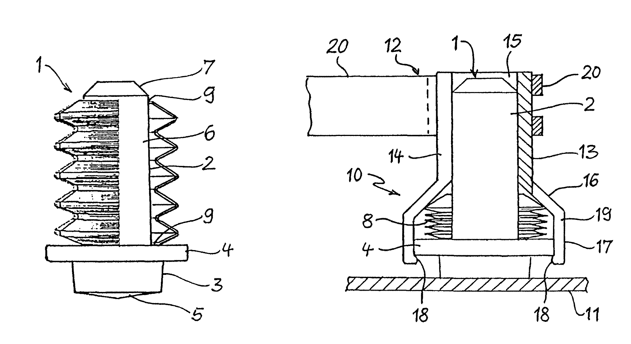
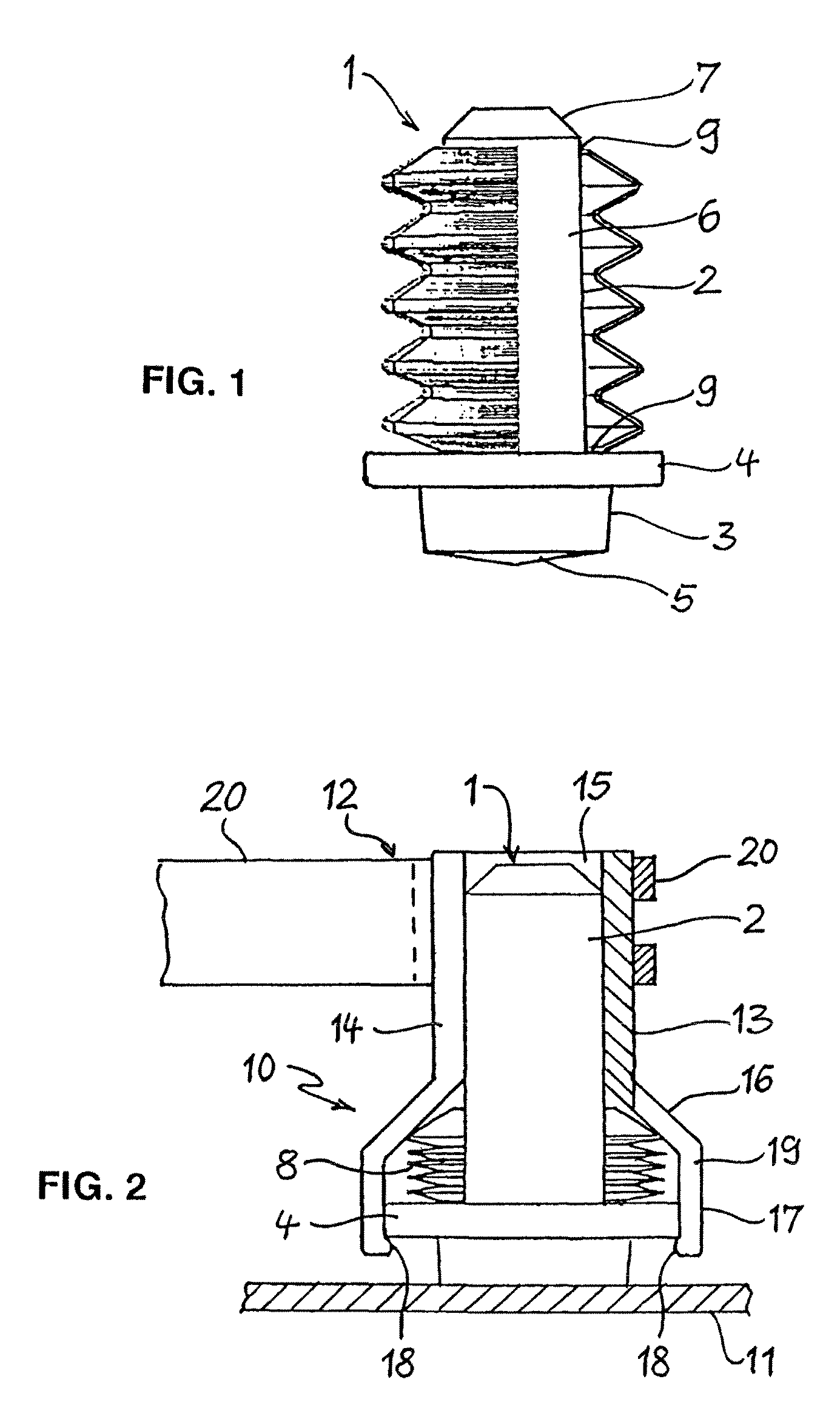
[0016]FIG. 1 shows a junction bolt 1 intended for use as a ground bolt in motor vehicles, and so configured that it can be connected to the vehicle bodywork by lift ignition welding. The junction bolt 1 has a shank 2 and a foot 3. The foot 3 has a larger diameter than the shank 2, and comprises at its end towards the shank 2 a flange 4 with circular outer contour. The end of the foot 3 away from the shank 2 is provided with an obtuse conical surface 5, whose vertex serves to produce a central are when the junction bolt 1 is welded on. In welding, the junction bolt 1 may be held to the flange 4 by means of a tongs transmitting the welding current to the junction bolt 1. The shank 2 has a smooth cylindrical outer surface 6 forming a surface of contact for attachment of a junction element. Instead of the smooth surface the o...


PUM


Abstract

Junction bolt having a shank and a foot arranged at one end of the shank and intended for attachment of the junction bolt to a part, the shank includes an outer surface forming a surface of contact for attachment of a junction element. The outer surface of the shank is surrounded by a protective sleeve covering the surface of contact on the shank and movable into a position in which the surface of contact is freely accessible.

Description

CROSS REFERENCE TO RELATED APPLICATIONS[0001]This application is a continuation of pending PCT Application No. PCT / EP2006 / 067902, filed Oct. 27, 2006 which claims priority from German Patent Application No. 10 2005 052 309.9, filed Nov. 1, 2005, the disclosures of which are incorporated herein by reference.BACKGROUND OF THE INVENTION[0002]The invention relates to a junction bolt, in particular a weld bolt, having a shank and a foot arranged at one end of the shank and intended for attachment of the bolt to a structural part. The invention relates further to a junction element and to a junction bolt and a junction element including an electrically conductive coupling device.[0003]In motor vehicles, so-called ground junctions are required in numerous locations, connecting electrical equipment arranged in the vehicle with the vehicle frame. The ground junctions generally have a junction bolt electrically conductively connected to the bodywork of the vehicle by welding or some other met...

Claims


Application Information

Patent Timeline
Patent Type & Authority Patents(United States)
IPC IPC(8): H01R13/52
CPCF16B33/004H01R4/66F16B37/061H01R2201/26
Inventor HAIN, JOCHENYAGCI, MAHZUNIPIMPER, RALFGEIST, JOACHIMSCHNEIDER, JOACHIM
Owner NEWFREY
Why Eureka
Try Eureka