Check patentability & draft patents in minutes with Patsnap Eureka AI!

Inverter for driving light source

a technology of inverter and light source, which is applied in the direction of light sources, instruments, lighting apparatuses, etc., can solve the problems of reducing the life of the piezoelectric blade itself and also the loading, and reducing the life of the hid lamp. , to achieve the effect of eliminating uniform brightness, reducing the impact of the piezoelectric blade, and reducing the brightness modulation range of the lamp tub

Inactive Publication Date: 2010-05-18
ZIPPY TECH
View PDF5 Cites 0 Cited by
  • Summary
  • Abstract
  • Description
  • Claims
  • Application Information

AI Technical Summary

Benefits of technology

[0003]Owing to the drawbacks in the prior art, the object of the present invention is to provide an inverter circuit for driving HID lamp tube, in which the impact on the piezoelectric blade can be reduced, so that the brightness modulation range of the lamp tube can be enlarged and the lamp tube also can eliminate an uniform brightness.
[0004]The present invention is related to an inverter for driving light source. The inverter includes a pulse control unit for producing a conduction period signal, a power switch unit driven by the conduction period signal and a power conversion unit for outputting a driving power, wherein after the inverter obtains an input power, the input power is transmitted to the power conversion unit through the conduction period of the power switch unit. The inverter is characterized in that a waveform modulation unit is further connected between the power switch unit and the power conversion unit, and the waveform modulation unit obtains the input power from the power switch unit and converts thereof into a modulation power, wherein the modulation power includes a positive edge modulation period with gradually rising voltage peak and a negative edge modulation period with gradually falling voltage peak, with the positive edge modulation period has a duration longer than that of the negative edge modulation period, and the modulation power is transmitted to the power conversion unit for being further converted into the driving power. Therefore, through the positive edge modulation period of the modulation power, the piezoelectric blade will not produce excess surge as initiation, and through the negative edge modulation period of the modulation power, the piezoelectric blade can receive a sufficient voltage drop, so that the outputted driving power can have sufficient voltage modulation range, thereby expending the brightness modulation range of the lamp tube and solving the problem of non-uniform brightness.

Problems solved by technology

However, the conventional driving method is disadvantageous of damaging the inverter and the light source.
When operation, except the filling gas and the fluorescent powder are related to the working efficacy of HID lamp, the power provided by the inverter for driving the lamp which rises and falls steeply also might reduce the life time of the HID lamp.
But, the square wave of power might cause the output voltage of the piezoelectric blade to have excess undulation, so as to reduce the life time of the piezoelectric blade itself and also the loading.
However, in this patent, when driving the loading in practice, owing to the added modulation energy, the falling of the waveform becomes smaller between the conduction (ON) and the disconnection (OFF), so that the brightness decrease of the lamp tube is limited due to the conversion characteristic of the piezoelectric blade, even the brightness of the lamp tube might become non-uniform.

Method used


Image

  • Inverter for driving light source
  • Inverter for driving light source
  • Inverter for driving light source

Examples


Embodiment Construction

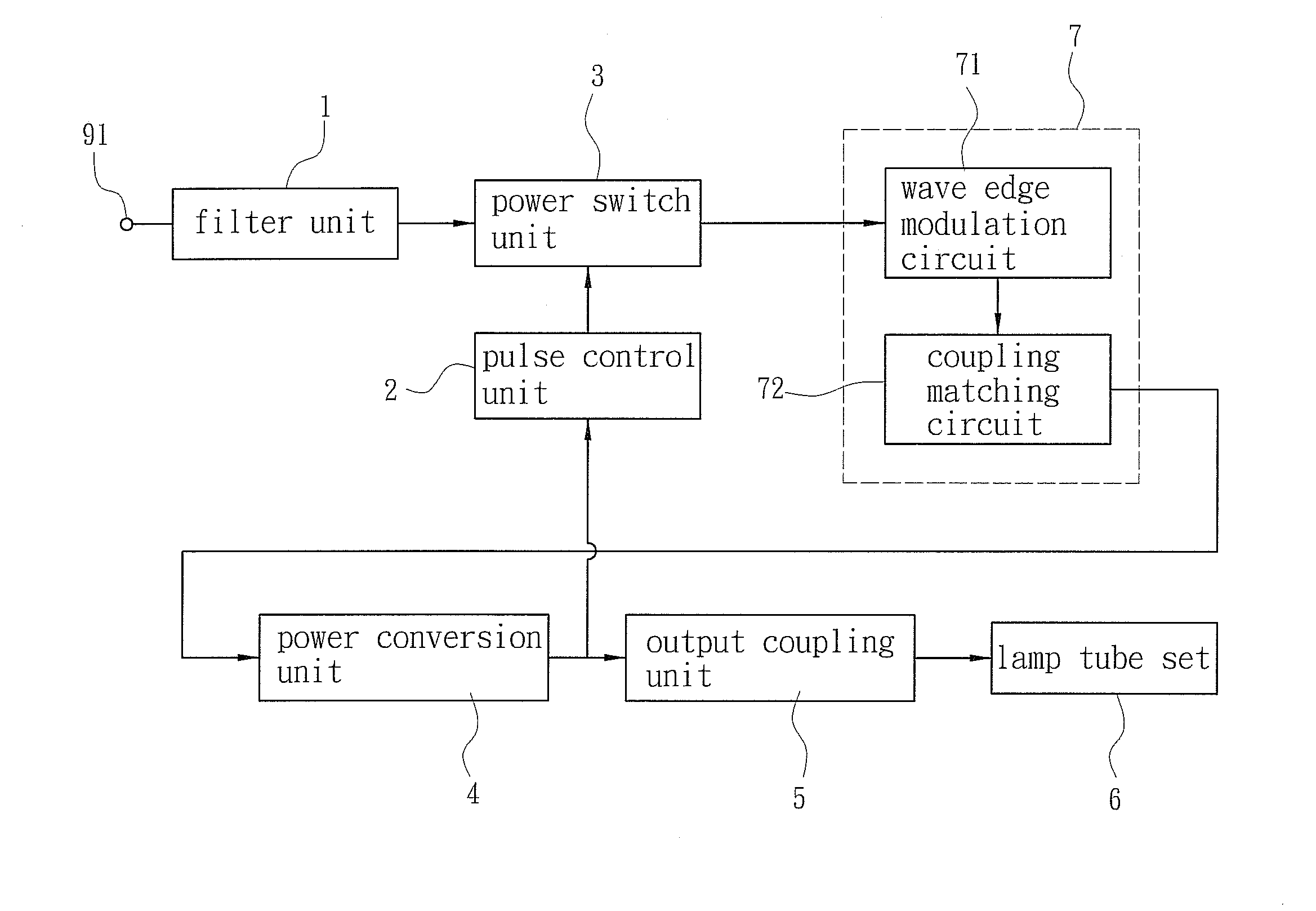
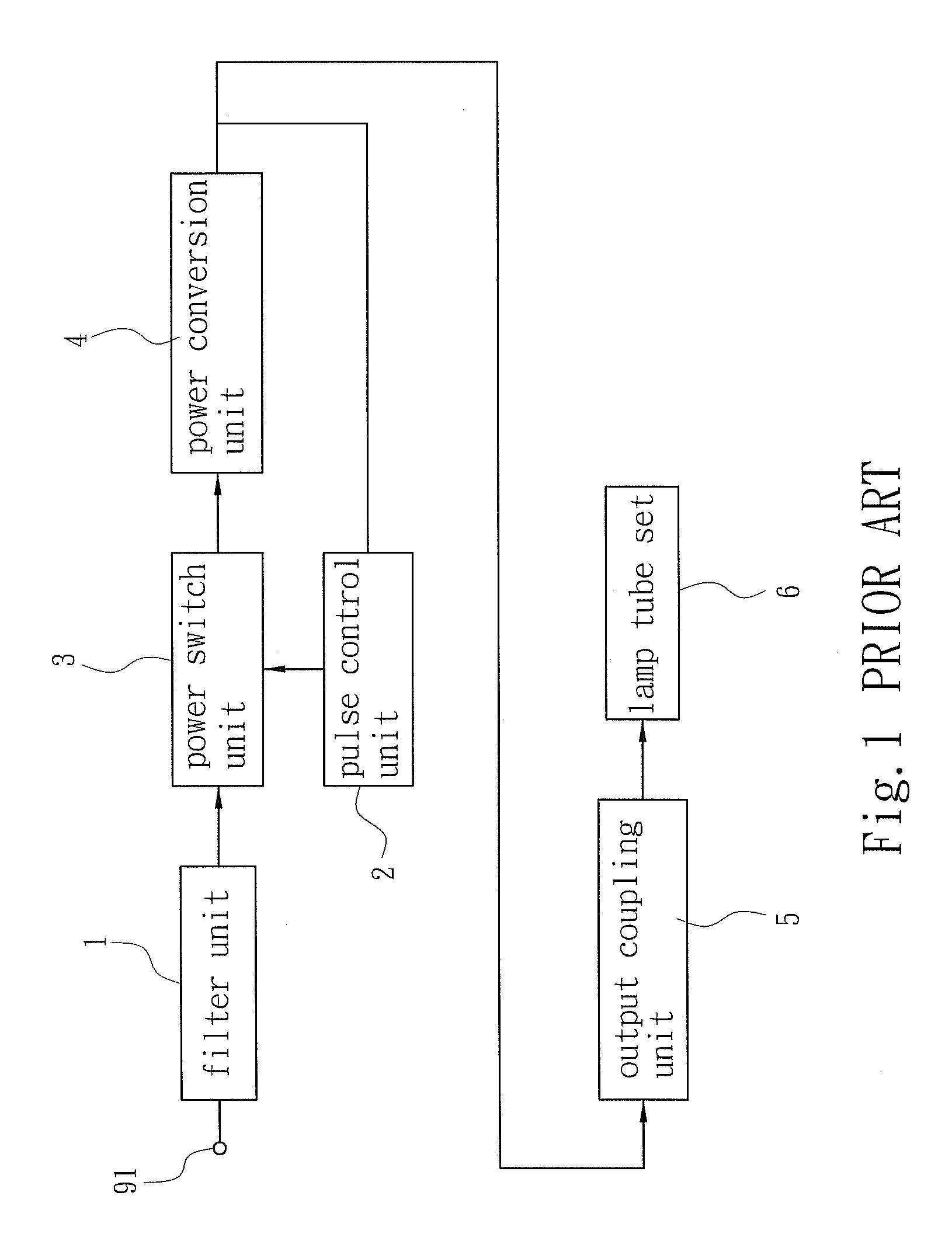
[0010]Please refer to FIG. 3. The present invention is related to an inverter for driving light source, wherein the inverter includes a pulse control unit 2 for producing a conduction period signal, a power switch unit 3 driven by the conduction period signal and a power conversion unit 4 for outputting a driving power. After the inverter obtains an input power 91 via a filter unit 1, the pulse control unit 2 utilizes the conduction period signal to drive the power switch unit 3, so that the input power 91 is transmitted to the power conversion unit 4 through the conduction period of the power switch unit 3. The inverter is characterized in that a waveform modulation unit 7 is further connected between the power switch unit 3 and the power conversion unit 4. Here, the waveform modulation unit 7 obtains the input power 91 from the power switch unit 3 and converts thereof into a modulation power, wherein the modulation power includes a positive edge modulation period 83 with gradually...


PUM


Abstract

An inverter for driving light source is disclosed. The inverter includes a pulse control unit for producing a conduction period signal, a power switch unit driven by the conduction period signal and a power conversion unit for outputting a driving power, wherein a waveform modulation unit is further connected between the power switch unit and the power conversion unit, and the waveform modulation unit obtains the input power from the power switch unit and converts thereof into a modulation power, wherein the modulation power includes a positive edge modulation period with gradually rising voltage peak and a negative edge modulation period with gradually falling voltage peak, with the positive edge modulation period has a duration longer than that of the negative edge modulation period, and the modulation power is transmitted to the power conversion unit for being further converted into the driving power.

Description

FIELD OF THE INVENTION[0001]The present invention is related to an inverter for driving a light source, and more particularly to an inverter circuit which can provide a driving power to drive a lamp.BACKGROUND OF THE INVENTION[0002]Currently, the light source mainly includes HID (High-Density Discharge) lamp and LED (Light Emitting Diode). For increasing the efficiency in lighting, the inverter used for driving light source is improved gradually. The circuit architecture of the convention inverter is shown in FIG. 1. The piezoelectric inverter includes a filter unit 1, a pulse control unit 2, a power switch unit 3 and a power conversion unit 4. After a DC input power 91 passes through the filter unit 1, the pulse control unit 2 through controlling the conduction period of the power switch unit 3, and further controls the power conversion unit 4 to convert the period of the input power 91. Then, the power conversion unit 4 provides the driving power, and the pulse control unit 2 draw...

Claims


Application Information

Patent Timeline
Patent Type & Authority Patents(United States)
IPC IPC(8): H05B37/02
CPCH05B41/2824
Inventor CHUNG, CHIN-BIAU
Owner ZIPPY TECH
Features
  • R&D
  • Intellectual Property
  • Life Sciences
  • Materials
  • Tech Scout
  • Unparalleled Data Quality
  • Higher Quality Content
  • 60% Fewer Hallucinations
Learn More