Low-loss tunable radio frequency filter

a radio frequency filter and low-loss technology, applied in the field of microwave circuits, can solve the problems of increasing the insertion loss of the filter, driving the size and cost of the resonator for a given, and corresponding compromise in filter steepness or selectivity, so as to minimize the insertion loss of the rf filter

Active Publication Date: 2010-05-18
MURATA MFG CO LTD
View PDF16 Cites 31 Cited by
  • Summary
  • Abstract
  • Description
  • Claims
  • Application Information

AI Technical Summary

Benefits of technology

[0015]In one embodiment, the variable non-resonant element(s) are configured for displacing the reflection zero(es) along the stop band to selectively move the pass band within the one sub-band. If a plurality of sub-bands are between the transmission zeroes, the variable non-resonant element(s) can be for displacing the reflection zero(es) along the stop band to create the pass band within selected ones of the sub-bands. Alternatively, or in addition to, the variable non-resonant element(s) can be for displacing at least another reflection zero within the stop band to create another pass band within another one of the sub-bands. In one embodiment, the pass band has substantially different bandwidths within the selected sub-bands. Although the present inventions should not be so limited in their broadest aspects, the ability to introduce a pass band within a selected one of the sub-bands by adjusting the variable non-resonant element(s), eliminates, or at least minimizes, the need to adjust the frequencies of the resonant elements, thereby decreasing the insertion loss incurred by the filter.
[0019]In accordance with a third aspect of the present inventions, a method of tuning a RF filter having a stop band that defines a tuning range is provided. The method comprises modifying the RF filter from a first frequency configuration to a second frequency configuration. When in the first frequency configuration, the RF filter has a first set of pass band characteristics within the tuning range, and when in the second frequency configuration, the RF filter has a second different set of pass band characteristics within the tuning range of the stop band. By way of non-limiting example, the first and second pass band characteristics having different center frequencies, different bandwidths, and / or different numbers of non-contiguous pass bands. In one method, the RF filter is modified from the first frequency configuration to the second frequency configuration by displacing at least one reflection zero within the stop band. In this case, the stop band has a plurality of transmission zeroes, and the at least one reference zero(es) is displaced in frequency more than the transmission zeroes are displaced in frequency. In this case, the insertion loss of the RF filter is minimized when modifying the RF filter from the first frequency configuration to the second frequency configuration.

Problems solved by technology

In particular, such electrical filters are used to select desired electrical signal frequencies from an input signal by passing the desired signal frequencies, while blocking or attenuating other undesirable electrical signal frequencies.
In most filter technologies, achieving a low insertion loss requires a corresponding compromise in filter steepness or selectivity.
This requirement for low resistance tends to drive the size and cost of the resonators for a given technology.
While this prior art technique has been generally successful in adjusting the frequency band, it inevitably introduces resistance into the resonators, thereby disadvantageously increasing the insertion loss of the filter.
Although HTS filters may be tuned without introducing significant resistance into the resonators by mechanically moving an HTS plate above each resonator in the filter to change its resonant frequency, such technique is inherently slow (on the order of seconds) and requires relative large three-dimensional tuning structures.
Insertion loss can be reduced in so-called switched filter designs; however, these designs still introduce a substantial amount of loss between switching times and require additional resonators.

Method used


Image

  • Low-loss tunable radio frequency filter
  • Low-loss tunable radio frequency filter
  • Low-loss tunable radio frequency filter

Examples


Embodiment Construction

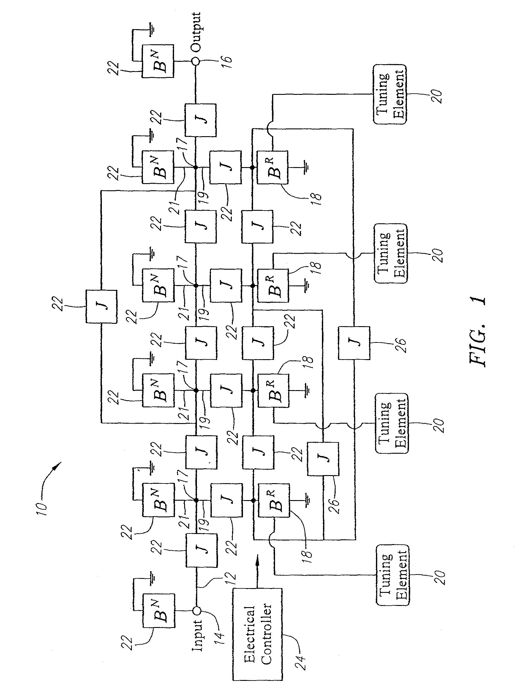
[0042]Referring to FIG. 1, a tunable radio frequency (RF) filter 10 constructed in accordance with the present inventions will now be described. In the illustrated embodiment, the RF filter 10 is a band-pass filter having pass band tunable within a desired frequency range, e.g., 800-900 MHz or 1,800-2,220 MHz. In a typical scenario, the RF filter 10 is placed within the front-end of a receiver (not shown) behind a wide pass band filter that rejects the energy outside of the desired frequency range. The RF filter 10 generally comprises a signal transmission path 12 having an input 14 and an output 16, a plurality of nodes 17 disposed along the signal transmission path 12, a plurality of resonant branches 19 respectively extending from the nodes 17, and a plurality of non-resonant branches 21 respectively extending from the nodes 17. The RF filter 10 further comprises a plurality of resonant elements 18 (in this case, four) between the input 14 and output 16, and in particular coupled...


PUM


Abstract

A tunable radio frequency (RF) filter is provided. The RF filter comprises a signal transmission path having an input and an output, a plurality of resonant elements disposed along the signal transmission path between the input and the output, and a plurality of non-resonant elements coupling the resonant elements together. The resonant elements are coupled together to form a stop band having a plurality of transmission zeroes corresponding to respective frequencies of the resonant elements, and at least one sub-band between the transmission zeroes. The non-resonant elements comprise at least one variable non-resonant element for selectively introducing at least one reflection zero within the stop band to create a pass band in one of the sub-bands(s). The variable non-resonant element(s) may be configured for displacing the reflection zero(es) along the stop band to selectively move the pass band within the one sub-band or within selected ones of the sub-bands.

Description

RELATED APPLICATION[0001]This application claims priority from U.S. Provisional Patent Application Ser. No. 60 / 737,878, filed Nov. 18, 2005, which is expressly incorporated herein by reference.FIELD OF THE INVENTION[0002]The present inventions generally relate to microwave circuits, and in particular, microwave band-pass filters.BACKGROUND OF THE INVENTION[0003]Electrical filters have long been used in the processing of electrical signals. In particular, such electrical filters are used to select desired electrical signal frequencies from an input signal by passing the desired signal frequencies, while blocking or attenuating other undesirable electrical signal frequencies. Filters may be classified in some general categories that include low-pass filters, high-pass filters, band-pass filters, and band-stop filters, indicative of the type of frequencies that are selectively passed by the filter. Further, filters can be classified by type, such as Butterworth, Chebyshev, Inverse Cheb...

Claims


Application Information

Patent Timeline
Patent Type & Authority Patents(United States)
IPC IPC(8): H01P1/20
CPCH01P1/20H01P1/20336H03H7/1791H03H7/12H03H7/0153H03H2210/012
Inventor TSUZUKI, GENICHIWILLEMSEN, BALAM A.
Owner MURATA MFG CO LTD
Why Eureka
Try Eureka