
Actuator, and lens unit and camera with the same

a technology of actuators and lens units, applied in the field of actuators, can solve the problems of increased manufacturing costs and inability to compact, and achieve the effect of allowing calibration operations

Inactive Publication Date: 2010-05-18
TAMRON
View PDF11 Cites 50 Cited by
  • Summary
  • Abstract
  • Description
  • Claims
  • Application Information

AI Technical Summary

Benefits of technology

"The present invention provides an actuator for a camera that can prevent image shake by translating and rotating an image-shake correcting lens within a plane parallel to the optical axis of the lens. The actuator includes a fixed member and a movable member with a position detecting means for detecting the position of the movable member. The position detecting means includes positioning receiving portions on the fixed member and positioning contact surfaces on the movable member that contact the positioning receiving portions when the movable member is in a calibration position. The actuator also includes a driving means for translating and rotating the movable member, and a calibration means for calibrating the position detecting means based on detection values from the position detecting means when the movable member is in the calibration position. The invention provides an improved actuator that can accurately position the image-shake correcting lens without causing discomfort to the user during calibration."

Problems solved by technology

Hence, the anti-shaking device cannot be compact and brings about an increased manufacturing cost.

Method used


Image

  • Actuator, and lens unit and camera with the same
  • Actuator, and lens unit and camera with the same
  • Actuator, and lens unit and camera with the same

Examples


first embodiment

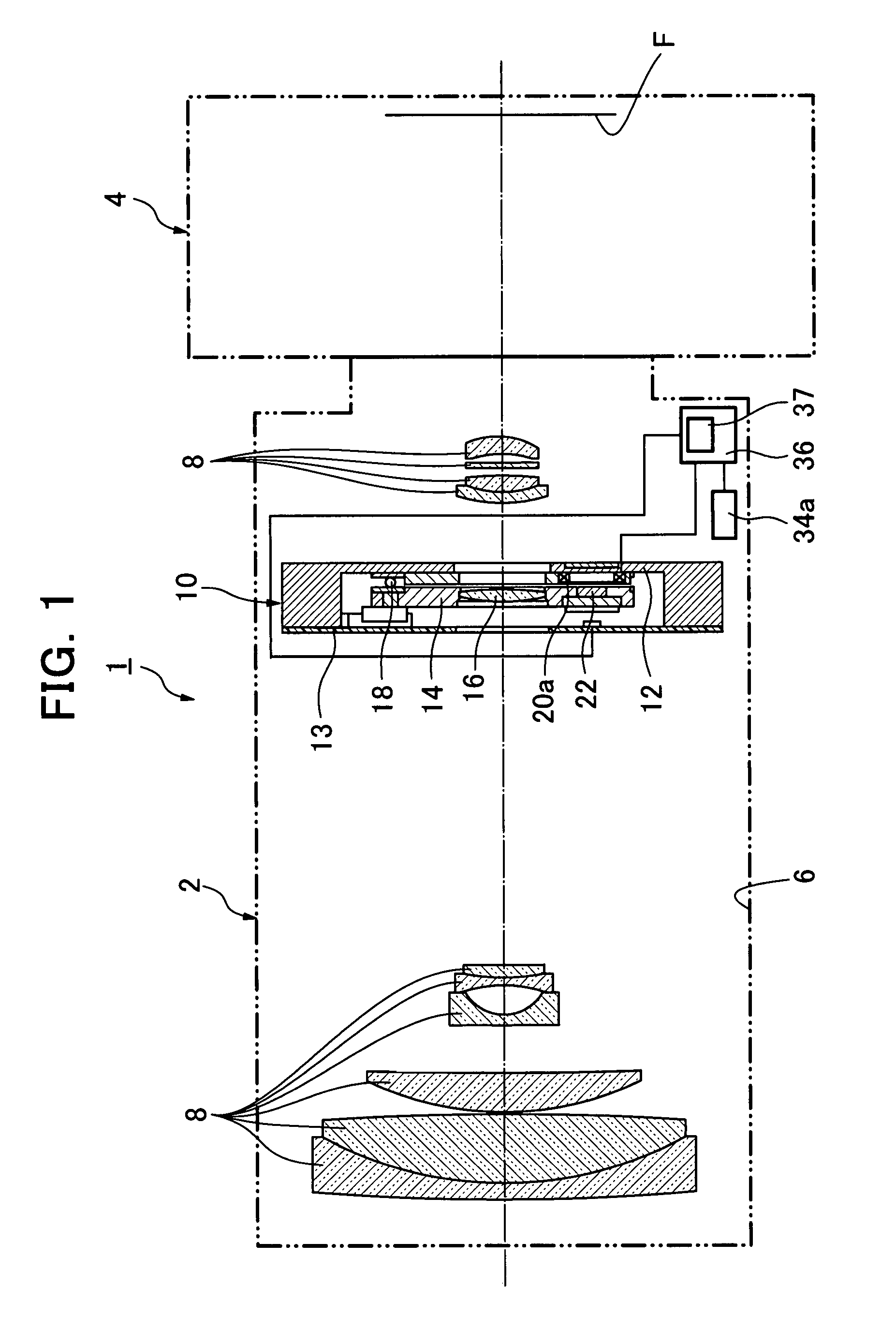
[0080]Referring to FIG. 1 and FIG. 8, operation of the camera 1 according to the present invention will be described. Initially, pressing a booting switch (not shown) in the camera 1 to turn on an anti-shake function, the actuator 10 integrated in the lens unit 2 is activated. The gyros 34a, 34b residing in the lens unit 2 momentarily detect vibrations of a predetermined frequency band and then produce the detection results to the arithmetic operation circuits 38a, 38b built in the controller 36. The gyro 34a produces signals representing an angular velocity of the lens unit 2 in yawing directions, to the arithmetic operation circuit 38a while gyro 34b produces those in pitching directions to the arithmetic operation circuit 38b. The arithmetic operation circuit 38a integrates the received signal or the angular velocity over time to calculate a yawing angle and calibrates the integration results on predetermined optical properties to generate the lens position command signal Dx desi...

second embodiment

[0100]As shown in FIG. 10, the actuator 110 used in camera has a fixed frame 112 serving as a stationary unit. The fixed frame 112 is provided with two sets of three positioning arms; i.e., a first set of three arms 115 and a second set of three arms 116. As can be seen in FIG. 10, the first set of the positioning arms 115 are separated from one another by 120 degrees along a circular extension of the fixed frame 112. Similar to this, the second set of the positioning arms 116 are equiangular from one another by 120 degrees along the circular extension of the fixed frame 112.

[0101]The positioning arms 115, 116 are provided with positioning receiving portions 115a, 116a, respectively, that are to come in contact with positioning projections 17 of a movable frame 14 or a movable member. The positioning receiving portions 115a, 116a are curved in a roughly arc-shaped surface, respectively, and an adjacent pair of the positioning receiving portions 115a and 116a are faced to each other....


PUM


Abstract

The present invention is directed to an actuator capable of retaining an image-shake correcting lens in a position(s) at which a calibration of lens optics can be affected, without additional locking means. The actuator (10) is capable of translating an image-shake correcting lens (16) so as to prevent an image from shaking, and the actuator is comprised of a fixed member (12), a movable member (14) provided with the image-shake correcting lens, supporting means (18) for supporting the movable member, a position detecting means (24, 25) for detecting a position of the movable member, a driving means (20, 22) for translating and rotating the movable member, a plurality of positioning receiving portions (15a) provided on the fixed member, a plurality of positioning contact surfaces (17a) disposed on the movable member and forced by a rotational movement of the movable member to mate and come in contact with the positioning receiving portions so that the movable member can be moved to a calibration position, and a calibrating means (37) for calibrating the position detecting means in response to detection values from the position detecting means that are received when the movable member is positioned at the calibration position.

Description

FIELD OF THE INVENTION[0001]The present invention relates to an actuator, and a lens unit and a camera with the actuator, and more particularly, it relates to an actuator capable of translating an image-shake correcting lens of a photographing optics within a plane orthogonal to an optical axis of the lens, and a lens unit and a camera with such an actuator.PRIOR ART[0002]Japanese Patent No. 2754872 (Patent Document 1) discloses an invention titled as “Anti-Shaking Device”. This anti-shaking device has a locking means, a movable member to be driven to suppress an image shaking, and a position detecting means. The movable member is locked by the locking means and the position detecting means is calibrated during the movable member is anchored at predetermined position.[0003]Japanese Patent Preliminary Publication No. H09-80537 (Patent Document 2) discloses an invention titled as “Shake Correcting Device”. This shake correcting device makes a shake-correcting optics translate till it ...

Claims


Application Information

Patent Timeline
Patent Type & Authority Patents(United States)
IPC IPC(8): G03B17/00
CPCG02B27/646H04N5/23248H04N5/23287H04N5/23258G03B2205/0069G03B2205/0015H04N23/68H04N23/6812H04N23/687
Inventor IWASAKI, TAKAFUMINOJI, TAKAYOSHITAKAGI, MASAYUKI
Owner TAMRON
Learn More