Manual tong

a hand tool and manual technology, applied in the direction of wrenches, drilling casings, drilling pipes, etc., can solve the problems of cumbersome man-handling, inappropriate modification of hand tools, and severe injury to any body in their path

Inactive Publication Date: 2010-05-25
DRILLROC PNEUMATIC PTY LTD
View PDF10 Cites 15 Cited by
  • Summary
  • Abstract
  • Description
  • Claims
  • Application Information

AI Technical Summary

Benefits of technology

[0034]Low capital equipment requirement for manufacture.
[0035]Design alteration, in the sense that different sizes are quickly and simply made by scaling the drawing and cutting the shapes, no re-tooling.
[0036]The strength of the tool can be modified, i.e.; the tool can be constructed of thinner plate to reduce the weight for the purpose of ease of handling or for a light duty application. Alternatively, it can be made of thicker and or higher grade plate for heaviest duty applications, even increasing or decreasing the number of plates to alter the strength and weight.

Problems solved by technology

Although relatively lightweight and easy to use, it is an inappropriate modification of a hand tool, and has become the accepted norm within the industry, notwithstanding the well documented injuries resulting from this unsafe practice.
These types of breakages are without warning as the component, whether faulty or overloaded, suddenly fails and the tool flies apart, severely injuring any body in its path.
A well known and regarded tool is manufactured by Petol Tool Co, but this tool also is not without its problems in that it is cumbersome to man-handle, and heavily reliant on expensive manufacturing techniques.
Although achieving this to a degree, in today's ever-cost conscious environment, it is still considered an expensive tool, due mainly to the extensive machining required in its manufacture.

Method used


Image

  • Manual tong
  • Manual tong
  • Manual tong

Examples


Embodiment Construction
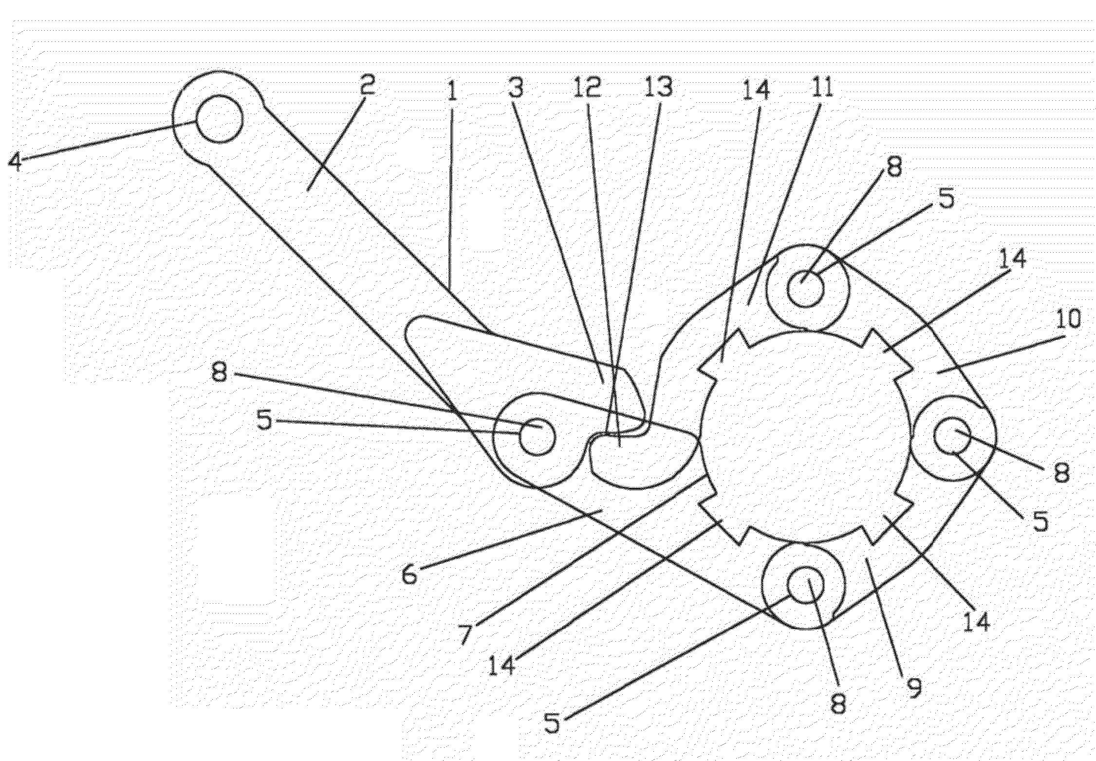
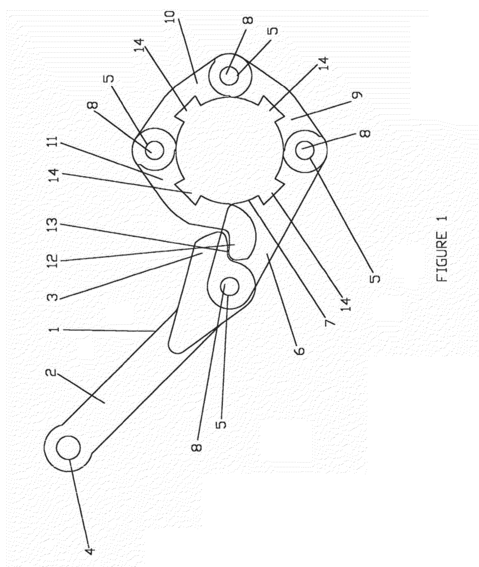
[0009]FIG. 1:

[0010]Is an orthographic view of the individual components in an assembled state, showing the normally concealed contact point 13 of head 3 with heel 12 constrained between at least two numbers of plate section 6. In this view can be seen the dovetail cutouts 14 which subsequently locate the jaw 15.
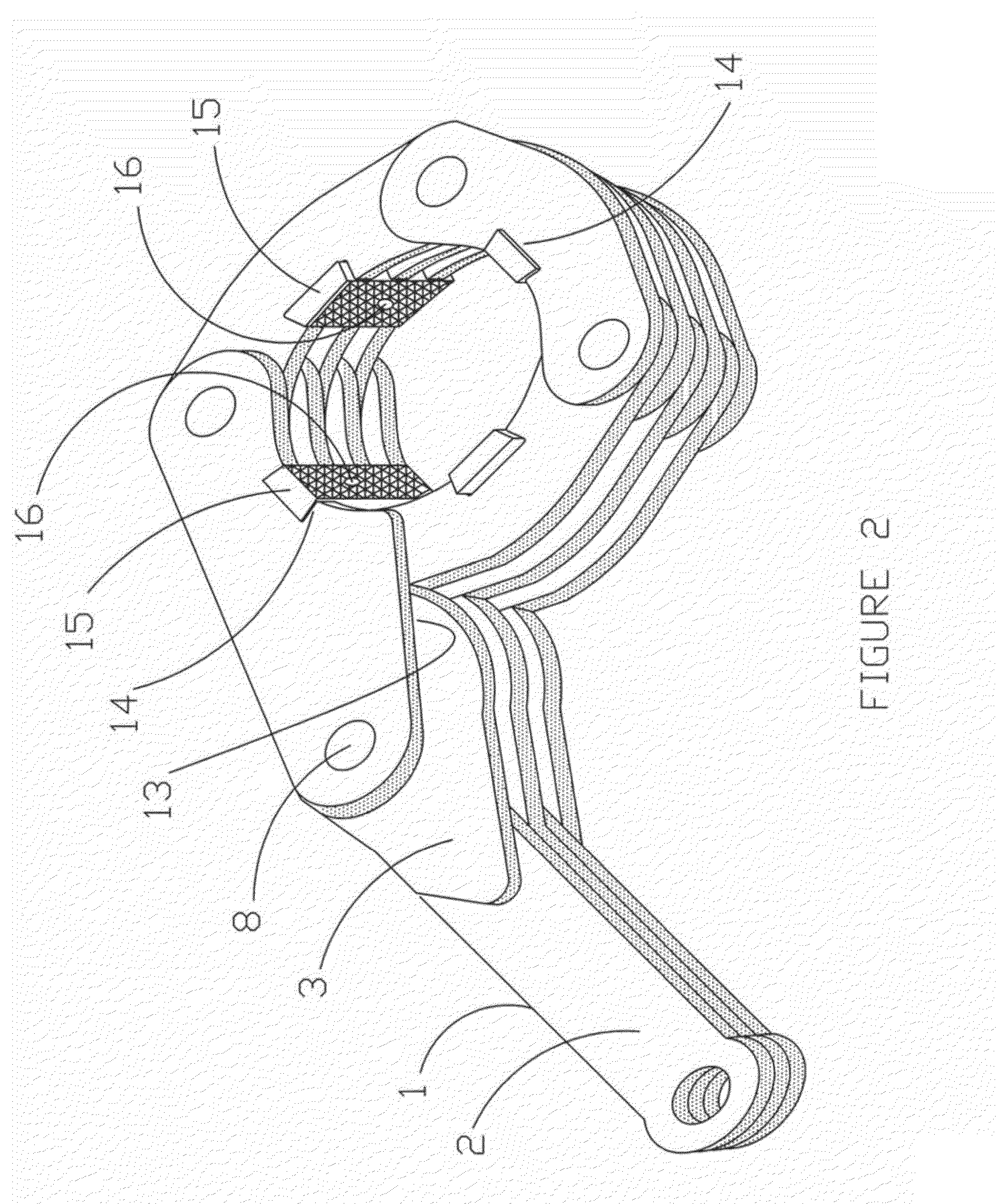
[0011]FIG. 2:

[0012]Shows a preferred embodiment of the invention in the horizontal plane with the jaw 15 and retainer 16, installed.

[0013]A load applied to lever 2 in a counter-clockwise direction will pivot handle assembly 1, consisting of a combination of lever 2 and head 3, about its pivot pin 8, to apply clamping force at 13, thereafter gripping and rotating the job.

[0014]FIG. 3:

[0015]Is an orthographic view of an embodiment of the invention, without jaws fitted,

[0016]permitting a greater scope of adjustment by the modification of at least one of components 6, 9, 10, 11, to incorporate at least one additional connection point 17.

[0017]FIG. 4:

[0018]For illustration and cla...


PUM


Abstract

A manually or mechanically / hydraulically operable tong of light weight and high load capacity by means of a multi-layer interlocking construction achieved by cutting the shapes from plate steel by known means, assembling the plate sections in suitable order, and retained with each other by cylindrical steel pins (8) forming a multi hinged tool capable of engaging the job circumference on two or more points equally via replaceable jaw dies (15) retained radially and axially.

Description

FIELD OF INVENTION[0001]This invention has particular application to the mining, rock drilling, waterwell drilling, and horizontal drilling industries, wherein the enormous torque loads encountered often create great difficulty when unscrewing drill stems and other drilling tools as retracting from the borehole. However, it is envisaged that the invention will be beneficial to other industries where circumferential high force gripping of cylindrically shaped objects is required.BACKGROUND OF THE INVENTION[0002]In reference to pipe handling tools used in the drilling industry, there are those generally referred to as ‘pipe tongs’ or ‘casing tongs’. Many of these are fully or semi automated units and are specific to the oil and gas drilling industry, and not within the scope of the present invention. Prior art tools relating to the present invention are more accurately described as ‘manual tongs’, ‘chain tongs’, ‘Petol tongs’, ‘BV tongs’, ‘Rapspan tong’, ‘pipe wrench’, or ‘stilson’, a...

Claims


Application Information

Patent Timeline
Patent Type & Authority Patents(United States)
IPC IPC(8): B25B13/00B25B13/50B25B13/52
CPCB25B13/5016E21B19/161B25B13/52
Inventor LORGER, TONYLORGER, DANIEL PAUL
Owner DRILLROC PNEUMATIC PTY LTD
Why Eureka
Try Eureka