Hollow cathode discharging apparatus

a cathode and discharge tube technology, applied in the direction of gas-filled discharge tubes, solid cathodes, coatings, etc., can solve the problems of slowing down film deposition, disadvantages, and affecting the discharge effect of cathodes, and achieves fast diffusion, high conductance, and easy transfer

Active Publication Date: 2010-05-25
IND TECH RES INST
View PDF7 Cites 7 Cited by
  • Summary
  • Abstract
  • Description
  • Claims
  • Application Information

AI Technical Summary

Benefits of technology

[0011]In light of the aforesaid drawbacks of the prior art, it is a primary objective of the present invention to provide a uniform gas distribution in a hollow cathode discharging apparatus.
[0012]Another objective of the present invention is to provide a hollow cathode discharging apparatus with high conductance high enough to facilitate scale-up of the apparatus in axial.
[0014]A further objective of the present invention is to provide a hollow cathode discharging apparatus adapted to generate high uniformity and high density plasma.
[0019]In comparison with the prior art, the present invention discloses the following: a spiral pathway defined with a gas distribution pipe and a hollow cathode electrode and winding through cathode openings along the axis of the hollow cathode electrode, such that the spiral pathway forms a plurality of continuous and communicated reaction chambers; a reactive gas is introduced into the reaction chambers through axially aligned gas separation apertures in such a way as to achieve axial uniform distribution of gas because the reaction chambers communicate with one another. The gas separation apertures aligned in a convection-enhancing way, coupled with the eccentric gas distribution pipe, allow the reactive gas to stay in the reaction chambers longer (i.e. longer residence time) and be uniformly distributed with a view to obtaining high-uniformity, high-density plasma; with the reaction chambers lying in an eccentric way, the gas distribution pipe with a large diameter has high conductance, such that the reactive gas is characterized by easy transfer, quick diffusion, and high uniformity, not to mention that the hollow cathode discharging apparatus of the present invention is capable of axial scale-up; and owing to the slender shapes, directions and relative positions of the anode openings and cathode openings, the resultant slender plasma jets are of high uniformity and high density. Accordingly, the present invention overcomes the drawbacks of the prior art and therefore has high industrial applicability and inventiveness.

Problems solved by technology

In so doing, the density of plasma decreases undesirably, thus slowing down the film deposition.
The disadvantage poses hindrance to large-area film deposition.

Method used


Image

  • Hollow cathode discharging apparatus
  • Hollow cathode discharging apparatus
  • Hollow cathode discharging apparatus

Examples


Embodiment Construction

[0027]The following specific embodiments are provided to illustrate the present invention. Persons skilled in the art can readily gain an insight into other advantages and features of the present invention based on the contents disclosed in this specification.

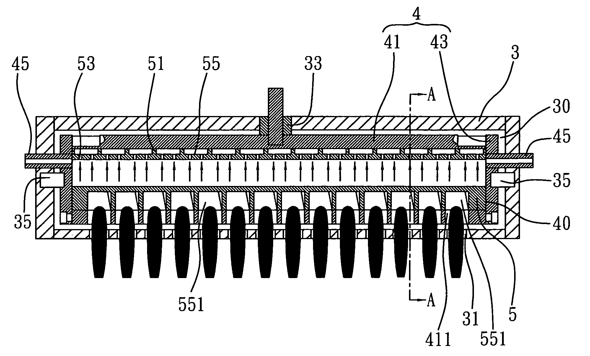
[0028]Referring to FIG. 4, a hollow cathode discharging apparatus of the present invention comprises: a hollow anode electrode 3 disposed with a first chamber 30 and a plurality of anode openings 31 communicating with the first chamber 30; a hollow cathode electrode 4 insulated from the hollow anode electrode 3, fixed in the first chamber 30, and disposed with a second chamber 40 and a plurality of cathode openings 411 communicating with the second chamber 40 and corresponding in position to the anode openings 31; and a gas distribution pipe 5 fixed in the second chamber 40, adapted to let in a reactive gas from outside of the hollow anode electrode 3 via an insulated gas pipe 45, wherein defined by the gas distribution pipe 5 ...


PUM

PropertyMeasurementUnit
frequencyaaaaaaaaaa
symmetryaaaaaaaaaa
frequencyaaaaaaaaaa

Abstract

The present invention provides a hollow cathode discharging apparatus including a hollow anode electrode, a hollow cathode electrode insulatedly fixed in the hollow anode electrode, a gas distribution pipe fixed in the hollow cathode electrode. The hollow anode electrode and the hollow cathode electrode are formed with anode openings and cathode openings respectively. Defined by the gas distribution pipe and the hollow cathode electrode and along the axis thereof is a spiral pathway winding through the cathode openings, so as to form a plurality of continuous and communicated reaction chambers. The gas distribution pipe is disposed with gas separation apertures communicated and adapted to introduce a reactive gas into the reaction chambers. The communicated reaction chambers enable uniform distribution of the reactive gas and thereby facilitate scale-up of the apparatus in axial. Accordingly, the present invention overcomes drawbacks of the prior art.

Description

BACKGROUND OF THE INVENTION[0001]1. Field of the Invention[0002]The present invention relates to a cathode discharging apparatus, and more particularly, to a hollow cathode discharging apparatus for generating low temperature slender plasma jets.[0003]2. Description of the Prior Art[0004]Hollow Cathode Discharge (HCD) is a common technique for generating low temperature plasma. Referring to FIG. 1, a conventional hollow cathode discharging apparatus 1 comprises a hollow anode electrode 11 and a hollow cathode electrode 13 enclosed by the hollow anode electrode 11. The hollow cathode electrode 13 is connected to a high frequency power generator 15 (for example, a high frequency power generator operable at a frequency of 13.56 MHz) and insulatedly spaced apart from the hollow anode electrode 11 by an insulated pipe 17 made of aluminum oxide ceramic. A reactive gas (for example, argon, helium, and nitrogen) required to generate plasma is introduced into the hollow cathode electrode 13 ...

Claims


Application Information

Patent Timeline
Patent Type & Authority Patents(United States)
IPC IPC(8): C23C16/00C23F1/00H01L21/306
CPCH01J37/32009H01J37/32596H01J37/3244
Inventor DU, CHEN-CHUNGCHIANG, MING-TUNGTUNG, FU-CHINGCHENG, CHIN-FENGSHEN, TEAN-MU
Owner IND TECH RES INST
Why Eureka
Try Eureka