Expandable intra-aortic balloon pump sheath

a balloon pump and expandable technology, applied in the field of medical devices, can solve possibly tissue necrosis, disruption of vessel plaque, and problems such as ischemia or interference, and achieve the effects of reducing the overall cross-sectional area or circumference, preventing binding or interference, and reducing the exterior cross-section

Active Publication Date: 2010-05-25
ONSET MEDICAL CORP
View PDF40 Cites 117 Cited by
  • Summary
  • Abstract
  • Description
  • Claims
  • Application Information

AI Technical Summary

Benefits of technology

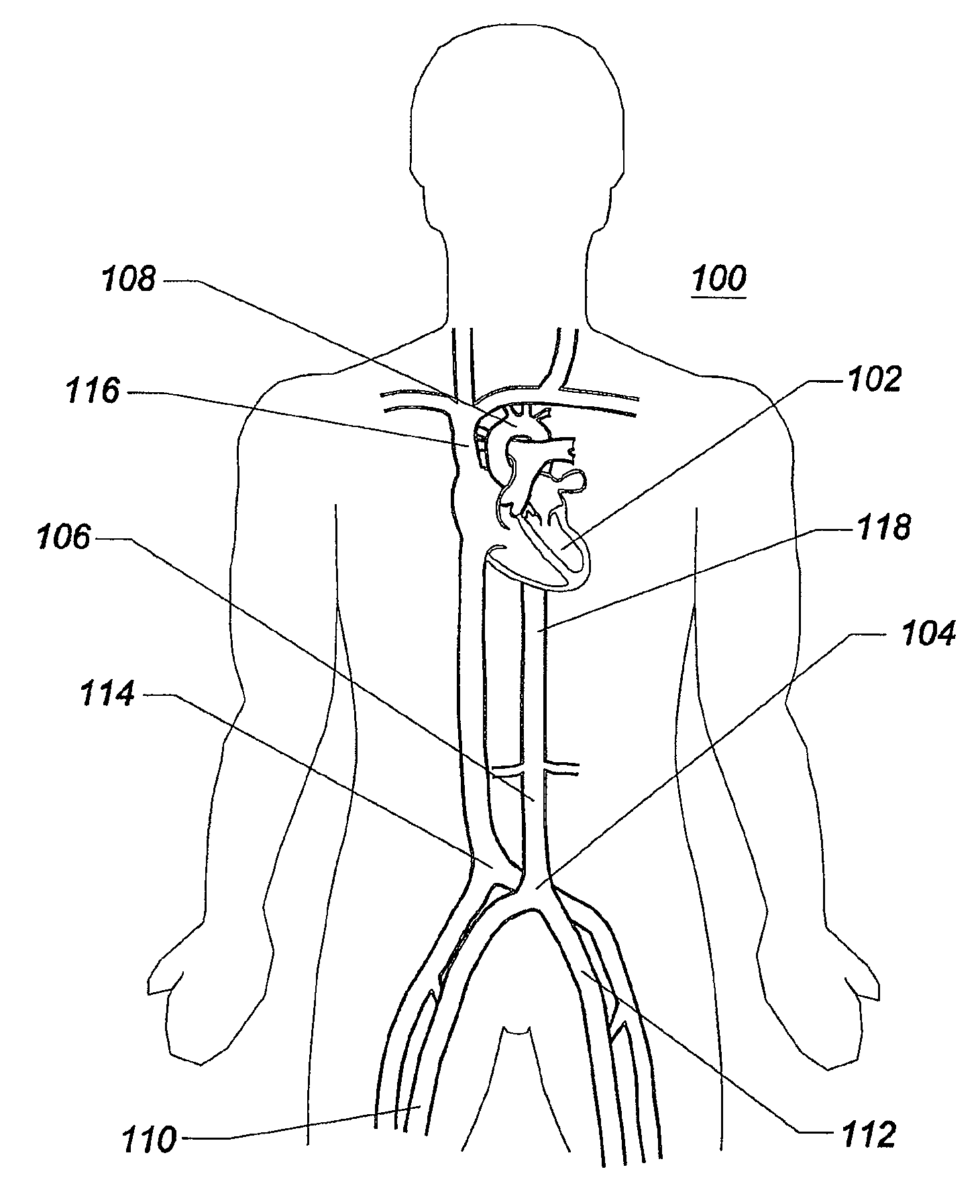
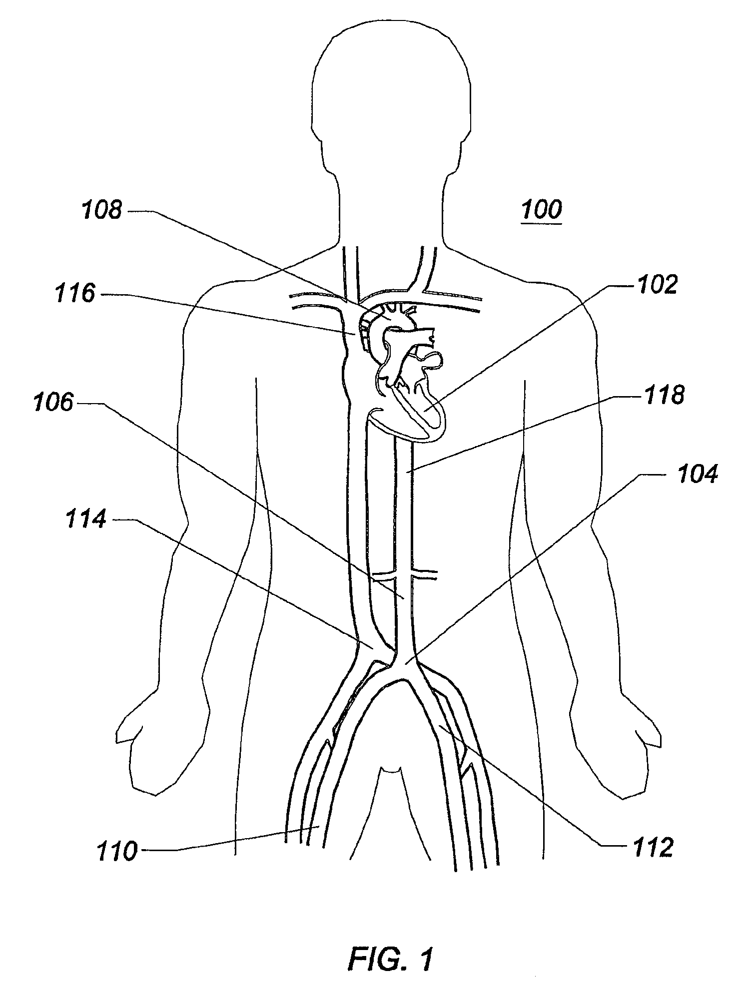
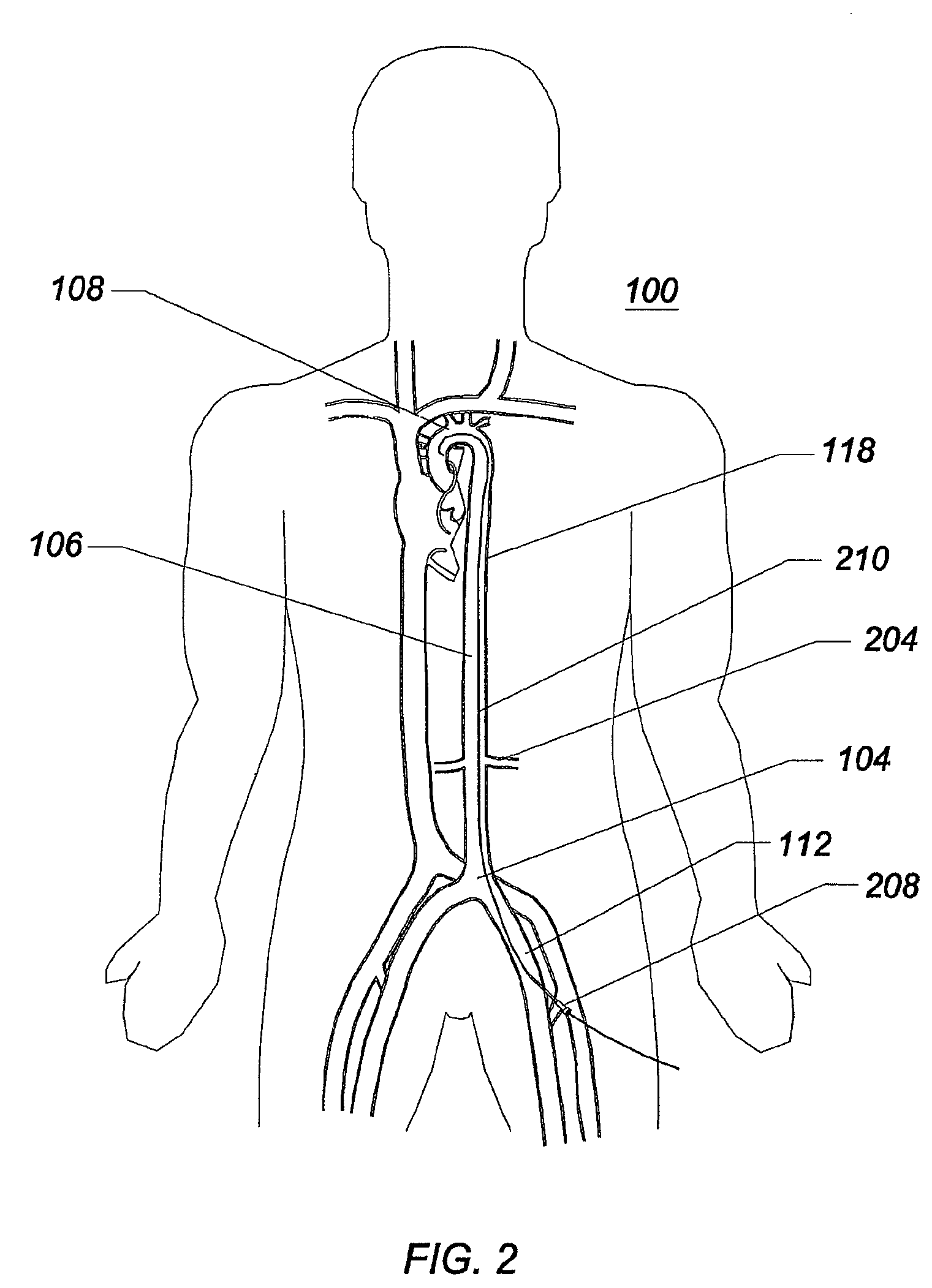
[0010]A transluminal, radially expanding access sheath is provided according to an embodiment of the invention. In an embodiment, the radially expanding sheath, or introducer, is used to provide access to the mammalian aorta by way of a femoral or iliac artery puncture and advancement retrograde toward the aortic arch through the arterial system. The mammalian aorta can be that of a human or human patient. A distal portion of the introducer or sheath is collapsed radially to minimize its outside diameter. A portion of the introducer or sheath, therefore, has a first, smaller cross-sectional profile that can be dilated to a second, larger cross-sectional profile. The catheter, introducer, or sheath can enter a vessel or body lumen with a diameter of 3 to 12 French or smaller, and allow passage of instruments through a central lumen that is 2 to 10 French. At the conclusion of the procedure, the sheath or catheter is capable of gently dilating its entire collapsed length, which can be a small portion of, or substantially the entire working length of the sheath or introducer. The sheath, introducer, or catheter, when expanded, can dilate the arterial puncture site using radially outwardly directed force and permit the removal of instrumentation therethrough, even when that instrumentation is large and unfurled. The sheath or catheter can be maximally visible under fluoroscopy and can be relatively inexpensive to manufacture. The sheath, catheter, or introducer can be kink-resistant and provide a stable or stiff platform for large catheter introduction therethrough.
[0011]In an embodiment, the sheath can have an introduction outside diameter that ranges from 3 to 15 French with a preferred range of 5 to 12 French. The inside diameter of the sheath can be expandable to permit instruments ranging up to 30 French to pass therethrough, with a preferred range of between 3 and 20 French. The sheath can have a working length ranging between 20-cm and 200-cm with a preferred length of 50-cm to 150-cm. The expandable distal end of the catheter can comprise between 5% and 95% of the overall working length of the catheter. The outside diameter of the proximal end of the catheter is generally larger than the outside diameter of the expanded distal end, due to increased wall thickness and reinforcement, to provide for pushability, torqueability (preferably approximately 1:1 torqueability), steerability, control, column strength, and the ability to easily pass large diameter instruments therethrough. In an embodiment, the sheath or introducer can be routed to its destination over one or more already placed guidewires with a diameter ranging from 0.010 inches up to 0.050 inches and generally approximating 0.032 to 0.038 inches in diameter.
[0012]An embodiment of the invention comprises an endovascular access system further comprising an axially elongate tubular body that defines a lumen extending from the proximal end to the distal end of the sheath. At least a portion of the elongate tubular body is expandable from a first, smaller cross-sectional profile to a second, greater cross-sectional profile. In an embodiment, the first, smaller cross-sectional profile is created by creating axially oriented folds in the sheath material. The expandable region can be the distal end, the proximal end, or both. These folds may be located in only one circumferential position on the sheath, or there may be a plurality of such folds or longitudinally oriented crimps in the sheath. The folds or crimps may be made permanent or semi-permanent by heat-setting the structure, once folded. In an embodiment, a releasable or expandable jacket is carried by the access sheath to restrain at least a portion of the elongate tubular structure in the first, smaller cross-sectional profile during insertion and up to or during inflation of the distal region. In another embodiment, the jacket is replaced by a packaging aid that is removed prior to inserting the sheath into the patient. In an embodiment, the elongate tubular body is sufficiently pliable to allow the passage of objects having a single maximum cross-sectional dimension larger than an inner diameter of the elongate tubular body in the second, greater cross-sectional profile. The adaptability to objects of larger dimension is accomplished by pliability or re-shaping of the cross-section to the larger dimension in one direction accompanied by a reduction in dimension in a lateral direction. The adaptability may also be generated through the use of malleable or elastomerically deformable sheath material. This re-shaping or non-round cross-section can be beneficial in passing two or more catheters through a single sheath with a minimum lateral cross-sectional area.

Problems solved by technology

Issues can arise, however, when the IABP is removed from the patient.
Such balloon wings have been reported to cause disruption of vessel plaque during removal or pullback through the aorta, iliac and femoral arteries.
This is especially problematic in very sick patients with significant vascular disease that involves plaque, mural thrombus, aneurysms, and other pathologies.
The disruption of a region of plaque or thrombus can cause emboli to break free from the vessel wall, float downstream, and lodge within the lumen of smaller distal vessels, blocking blood flow, and resulting in ischemia and possibly tissue necrosis.

Method used


Image

  • Expandable intra-aortic balloon pump sheath
  • Expandable intra-aortic balloon pump sheath
  • Expandable intra-aortic balloon pump sheath

Examples


Embodiment Construction

[0049]The invention may be embodied in other specific forms without departing from its spirit or essential characteristics. The described embodiments are to be considered in all respects only as illustrative and not restrictive. The scope of the invention is therefore indicated by the appended claims rather than the foregoing description. All changes that come within the meaning and range of equivalency of the claims are to be embraced within their scope.

[0050]The invention, which can be generally termed a catheter or a sheath, can be described as being an axially elongate hollow tubular structure having a proximal end and a distal end. The axially elongate structure further has a longitudinal axis and has an internal through lumen that extends from the proximal end to the distal end for the passage of instruments, fluids, tissue, or other materials. The axially elongate hollow tubular structure is generally flexible and capable of bending, to a greater or lesser degree, through one...


PUM


Abstract

Disclosed is an expandable transluminal sheath, for introduction into the body while in a first, low cross-sectional area configuration, and subsequent expansion of at least a part of the distal end of the sheath to a second, enlarged cross-sectional configuration. The sheath is configured for use in the vascular system and has utility in the introduction and removal of balloon counterpulsation catheters. The access route is through the femoral arteries and the iliac arteries into the aorta, where an intra-aortic balloon pump catheter is positioned to provide cardiac support. The distal end of the sheath is maintained in the first, low cross-sectional configuration during advancement to the arteries into the aorta. The distal end of the sheath is subsequently expanded using a radial dilatation device.

Description

PRIORITY CLAIM[0001]This application claims priority to U.S. Provisional Patent Application Ser. No. 60 / 887,112, filed on Jan. 29, 2007, titled Expandable Intra-Aortic Balloon Pump Sheath, the entirety of which is hereby incorporated herein by reference.BACKGROUND OF THE INVENTION[0002]1. Field of the Invention[0003]The invention relates to medical devices for percutaneously accessing body lumens and, more particularly, to methods and devices for accessing the cardiovascular system. In one application, the invention relates to methods and devices for introducing and removing large balloon catheters and instruments, particularly intra-aortic balloon pumps, into and from a patient.[0004]2. Description of the Related Art[0005]A wide variety of diagnostic or therapeutic procedures involves the introduction of a device into the vasculature through a percutaneous incision at an access site. Such regions of the vasculature, preferred for access, include both the arteries and veins, typical...

Claims


Application Information

Patent Timeline
Patent Type & Authority Patents(United States)
IPC IPC(8): A61M5/178A61M29/00A61M37/00
CPCA61M25/0662A61M2025/0024
Inventor LENKER, JAY A.BISHOP, JOSEPHKICK, GEORGE F.NANCE, EDWARD J.
Owner ONSET MEDICAL CORP
Why Eureka
Try Eureka