
Defoaming method, defoaming device and manufacturing method of transfer mold

a technology of degasification device and manufacturing method, which is applied in the direction of liquid degasification, separation processes, manufacturing tools, etc., can solve the problems of affecting the dimensional accuracy of the distance between ribs, the inability to accurately execute transferring, etc., and achieve the effect of deteriorating and maintaining the flatness of the metallic mold

Inactive Publication Date: 2010-05-25
3M INNOVATIVE PROPERTIES CO
View PDF20 Cites 8 Cited by
  • Summary
  • Abstract
  • Description
  • Claims
  • Application Information

AI Technical Summary

Benefits of technology

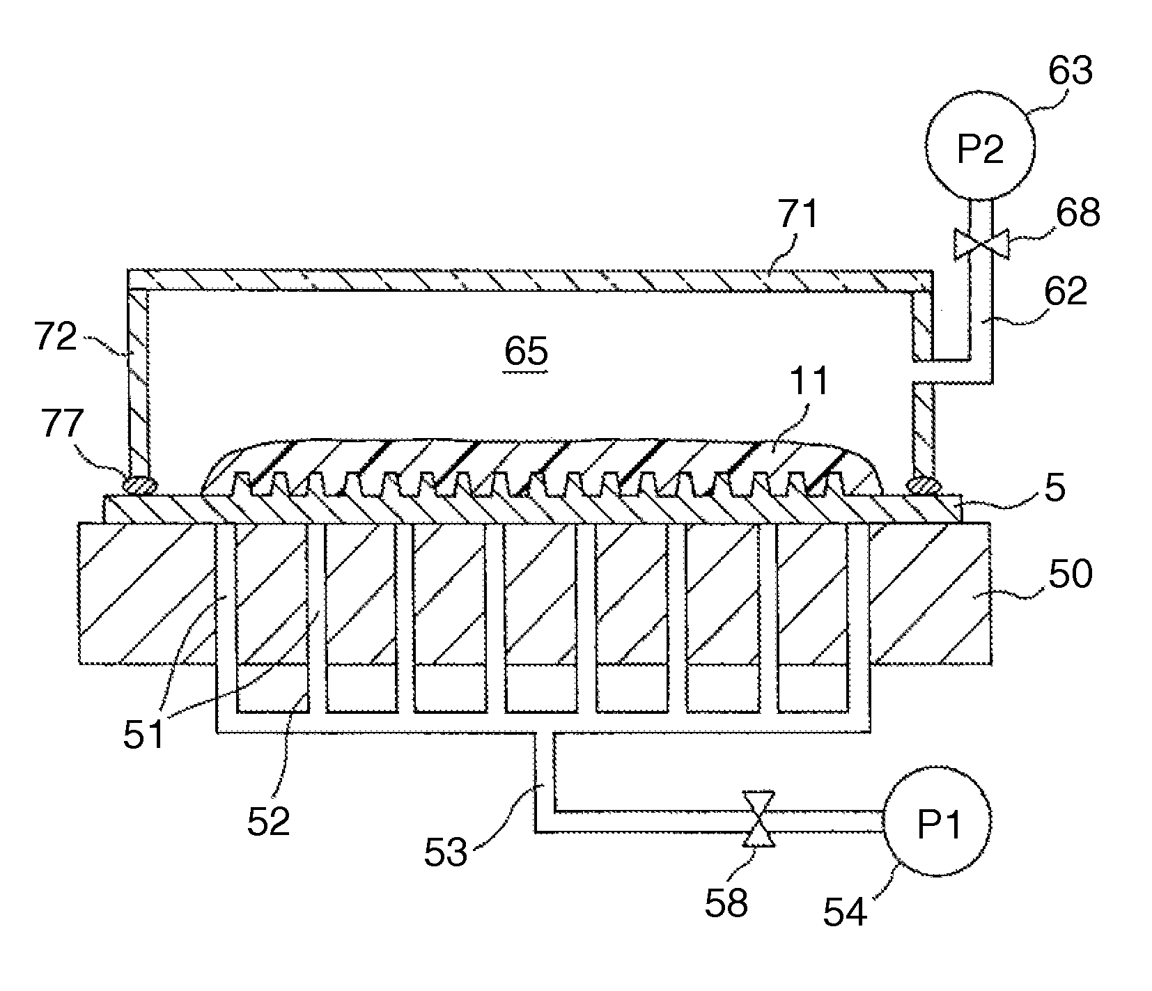
[0011]The present invention has been intended to solve the above problems of the prior art. An object of the present invention is to provide a defoaming method and a defoaming device for removing air bubbles from a curable resin material and from a contact portion of the resin material with an irregularity structure of a flat metallic mold which has a fine irregularity structural region and a flat region in the periphery of the fine irregularity structural region and which has the curable resin material applied thereto by filling the resin material into the irregularity structure of the fine structural region, which enable to remove a possibility that the resin material spreads onto the back side of the metallic mold and the flatness of the metallic mold is deteriorated, and a possibility that the metallic mold is deformed.
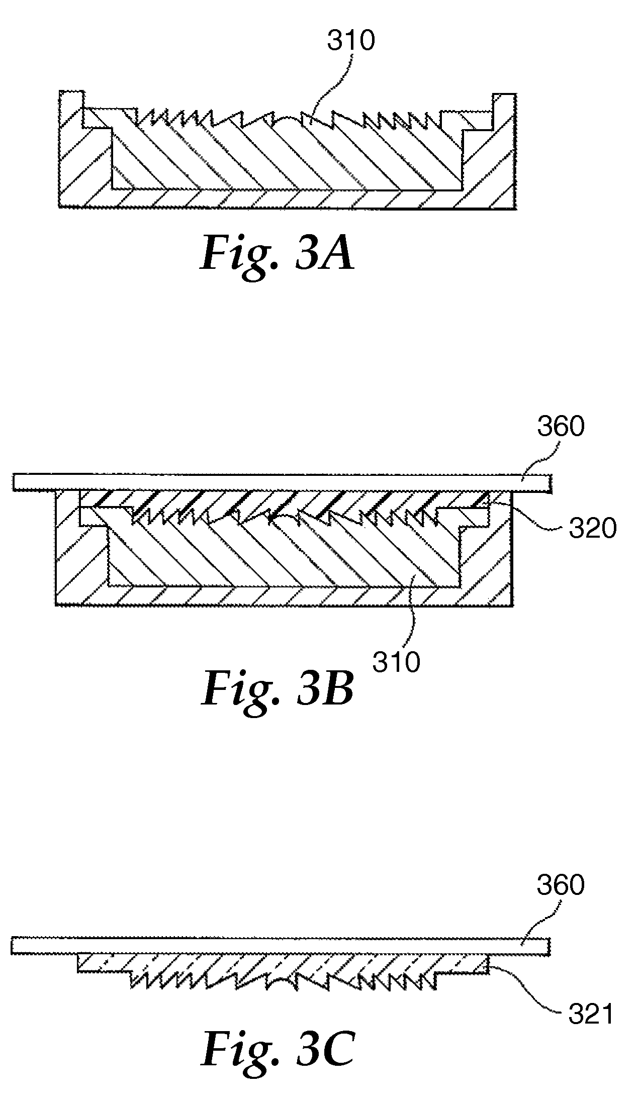
[0012]It is another object of the present invention to provide a method of manufacturing a transfer mold (shaping mold) which is especially advantageously used for manufacturing PDP ribs, with high accuracy and at a high yield. Still another object of the present invention is to provide such a manufacturing method capable of reducing manufacturing steps without using complicated fabrication steps and without requiring a skill.
[0035]As can be understood from the following detailed explanations of the present invention, according to the present invention, as an airtightly closed space is defined only in a fine structural region having an irregularity structure on a surface of a flat metallic mold (a flat plate-type mold), there is no possibility that an end portion of the flat metallic mold, which portion is thin and has a large area, is raised by an air current during vacuum defoaming, and thus enabling to maintain the flatness of the metallic mold. Further, there is no possibility that air spreads into between the metallic mold and the mold platen which supports the metallic mold, thereby deteriorating the flatness of the metallic mold. Furthermore, as it becomes possible to prevent the occurrence of such a problem that the resin material flows outside the metallic mold and spreads into between the metallic mold and the mold platen, the flatness of the metallic mold can be maintained. Furthermore, since the airtightly closed space can be diminished, defoaming of resin material can be quickly carried out.
[0036]Furthermore, according to the present invention, as suction holes are provided on a mold platen on which the metallic mold is set and then vacuum defoaming is executed while the metallic mold is being fixed by a suction force, it becomes possible to prevent the metallic mold from being deformed during the defoaming process in which vacuum or decompression is applied to the airtightly closed space.

Problems solved by technology

In the case where the flexible mold is manufactured in the way described above, since the photo-curable material is only coated on the metallic mold, air bubbles are incorporated into the resulting photo-curable material layer, and thus it becomes impossible to accurately executing transferring.
That is, when the flatness of the metallic mold is deteriorated, irregularities caused by the deterioration of the flatness are transferred onto the resulting mold as they are and the dimensional accuracy of a distance between ribs is greatly affected.

Method used


Image

  • Defoaming method, defoaming device and manufacturing method of transfer mold
  • Defoaming method, defoaming device and manufacturing method of transfer mold
  • Defoaming method, defoaming device and manufacturing method of transfer mold

Examples


Embodiment Construction

[0047]The defoaming method, the defoaming device and the transfer mold of the present invention can be advantageously executed in various embodiments. Referring to the manufacture of PDP rib which is a typical example of the fine structural body, an embodiment of the present invention will be explained in detail centering around the manufacture of a flexible transfer mold. In this connection, the transfer mold, to which the defoaming method and the defoaming device of the present invention can be applied, is not necessarily limited to a flexible mold but the transfer mold can be applied to other types of molds, for example, rigid molds. Further, the use of the transfer mold of the present invention is not necessarily limited to the manufacture of PDP ribs but the transfer mold can be used for the manufacture of other fine structural bodies.

[0048]Before the defoaming method and the defoaming device of the present invention are explained, explanations will be made with regard to a fle...


PUM

PropertyMeasurementUnit
thicknessaaaaaaaaaa
thicknessaaaaaaaaaa
lengthaaaaaaaaaa

Abstract

A defoaming method for removing air bubbles from a curable resin material and a contact portion of the resin material with an irregular structure of a flat metallic mold. The mold includes a fine structural region having a fine irregular structure and a flat region in the periphery of the fine structural region. The curable resin material is applied to the irregular structure of the fine structural region, filling the irregular structure with the resin material.

Description

TECHNICAL FIELD[0001]The present invention relates to a defoaming method and a defoaming device. More particularly, the present invention relates to a defoaming method and a defoaming device for removing air bubbles from a curable resin material and an irregularity structural portion of an original shaping mold, which will be referred to as a “flat metallic mold” hereinafter, in the production of a transfer mold of a three (3)-dimensional structure having a fine irregularity structure on the surface thereof from a curable resin material. The present invention also relates to a method of manufacturing a transfer mold, used for transfer, having on a surface thereof a fine irregularity structure of a three dimensional structure corresponding to the flat metallic mold, by the transfer technique, wherein a curable resin material is filled in the flat metallic mold having a fine irregularity structure on the surface with using the above defoaming method. The transfer mold of the present i...

Claims


Application Information

Patent Timeline
Patent Type & Authority Patents(United States)
IPC IPC(8): B01D19/00B29C48/76
CPCB29C33/424B29C35/0888B29C37/006B29C2791/006B29C2035/0827B29C37/0053
Inventor AOKI, TORUKIKUCHI, HIROSHIYODA, AKIRA
Owner 3M INNOVATIVE PROPERTIES CO
Learn More