Street light auxiliary power converter for ancillary devices

a technology of auxiliary power converter and street light, which is applied in the direction of circuit arrangement, energy-efficient lighting, sustainable buildings, etc., can solve the problems of complicated sales and device inventory control

Active Publication Date: 2010-05-25
SUNRISE TECH
View PDF3 Cites 31 Cited by
  • Summary
  • Abstract
  • Description
  • Claims
  • Application Information

AI Technical Summary

Benefits of technology

[0009]Another object of the present invention is to provide a system and a device to allow customers to select the nature of the output tapped from the primary source so that their application can be applied to a properly equipped source without requiring internal or additional transformation / rectification.

Problems solved by technology

This, in fact, required manufactures of such devices to either provide either internal or external transformer / rectification means, both of which complicate sales and device inventory control.

Method used


Image

  • Street light auxiliary power converter for ancillary devices
  • Street light auxiliary power converter for ancillary devices
  • Street light auxiliary power converter for ancillary devices

Examples


Embodiment Construction

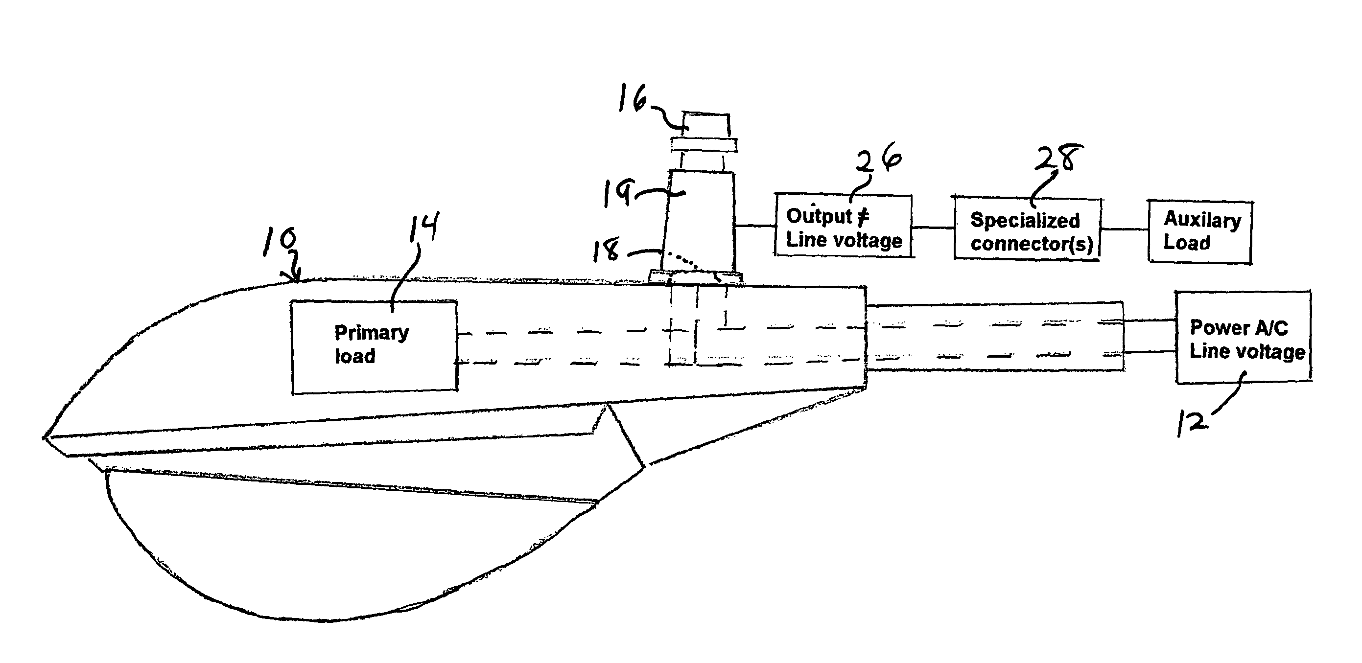
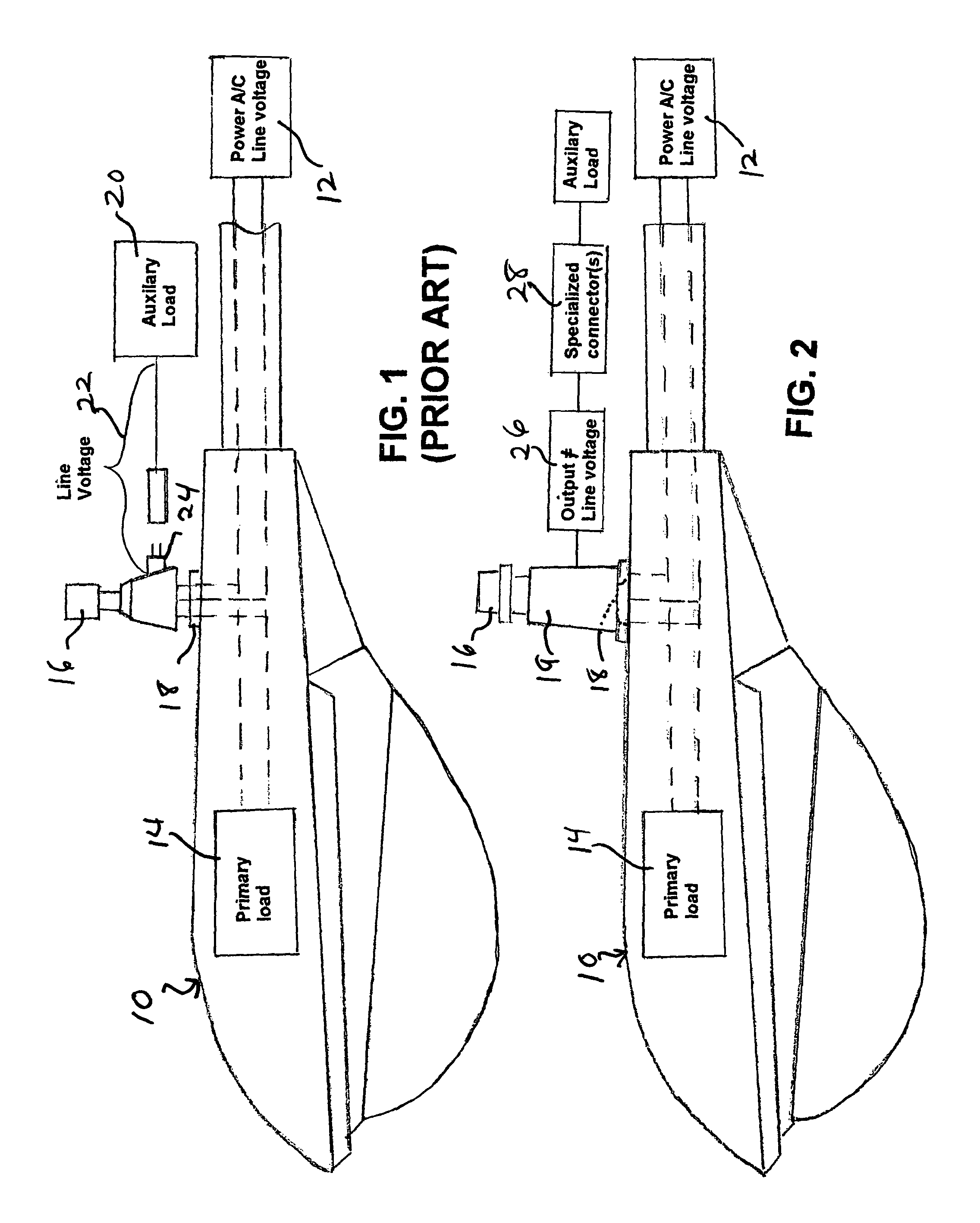
[0022]For quite some time both public and private authorities recognize the advantages of tapping power from street and area lights for various purposes. The problem was that, in many instances, the devices using the power in an auxiliary manner did not have the same timing requirements as the street or area lights themselves. For this reason, retrofit devices were established, such as that shown as reference numeral 10 in FIG. 1, which would allow the auxiliary devices to be turned on and off on a schedule different from the schedule developed for the street or area lights themselves. Hence, in FIG. 1, the line voltage is provided to an auxiliary device 20 and can be manipulated temporally (that is, shut on and off) at intervals independently from the control device 16 used for the street or area light itself 14.

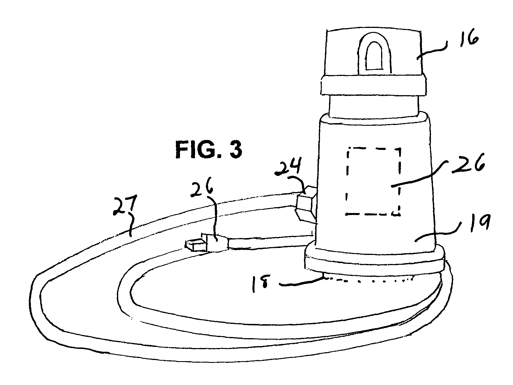
[0023]The present invention shown in FIG. 2 generally as numeral 10 is different from the prior art in that, between the connection to the main power source 12 (which is at...


PUM


Abstract

A system and device for using the power provided to street and area lights or other outdoor installations to power auxiliary devices which require a power supply which is different from line voltage for their power requirements. A device adapted to be connected to the NEMA three pole receptacle on a street or area light which converts the line voltage provided to the outdoor installation into a power form required by one or more auxiliary devices which cannot directly use the line current or voltage. The appropriate electrical connector for the auxiliary device may be included. Among the conversions: line voltage up to 480 volts alternating current converted to a user's specified voltage for WiFi, radios, surveillance cameras, traffic monitoring, other monitoring, security cameras, other communications, and UPS systems; DC voltage for the above applications and others; and power over ethernet conversion (for example, 48 volt direct current, 420 milliamperes).

Description

CROSS-REFERENCE TO RELATED APPLICATIONS[0001]This application claims the benefit under 35 U.S.C. §119(e) of prior U.S. Provisional Application No. 60 / 798,578 filed May 8, 2006; which is hereby incorporated by reference.STATEMENT REGARDING FEDERALLY SPONSORED RESEARCH OR DEVELOPMENT[0002]This invention has been created without the sponsorship or funding of any federally sponsored research or development program.FIELD OF THE INVENTION[0003]This invention concerns the use of power supplied to external or outdoor lighting systems, such as street and area lamps, for additional or ancillary purposes.BACKGROUND OF THE INVENTION[0004]Street and outdoor area lights are installed either by the government or by private entities to provide illumination for safety, recreation, security, and other purposes. Such lights are often fitted with a National Electrical Manufactures Association locking three pole receptacle. This receptacle often accepts a twist lock photocontrol to control individual li...

Claims


Application Information

Patent Timeline
Patent Type & Authority Patents(United States)
IPC IPC(8): H02J3/00
CPCH05B37/00Y10T307/258Y10T307/25Y02B20/72H05B47/11H05B47/20Y02B20/40
Inventor SPILLMAN, VANCEROSENQUIST, CRAIGBARBER, JEREMY BELKNAP
Owner SUNRISE TECH
Why Eureka
Try Eureka