
Systems and methods for compensation for a dynamic axle load transfer

a dynamic axle and load transfer technology, applied in the field of dynamic axle load transfer system and compensation method, can solve the problems of not being able to control the vehicle as desired by the driver, thereby extremely heavy not following linear operating points, etc., to achieve the effect of reducing the load on the front axle, and reducing the risk of oversteering

Inactive Publication Date: 2010-05-25
GM GLOBAL TECH OPERATIONS LLC
View PDF7 Cites 8 Cited by
  • Summary
  • Abstract
  • Description
  • Claims
  • Application Information

AI Technical Summary

Benefits of technology

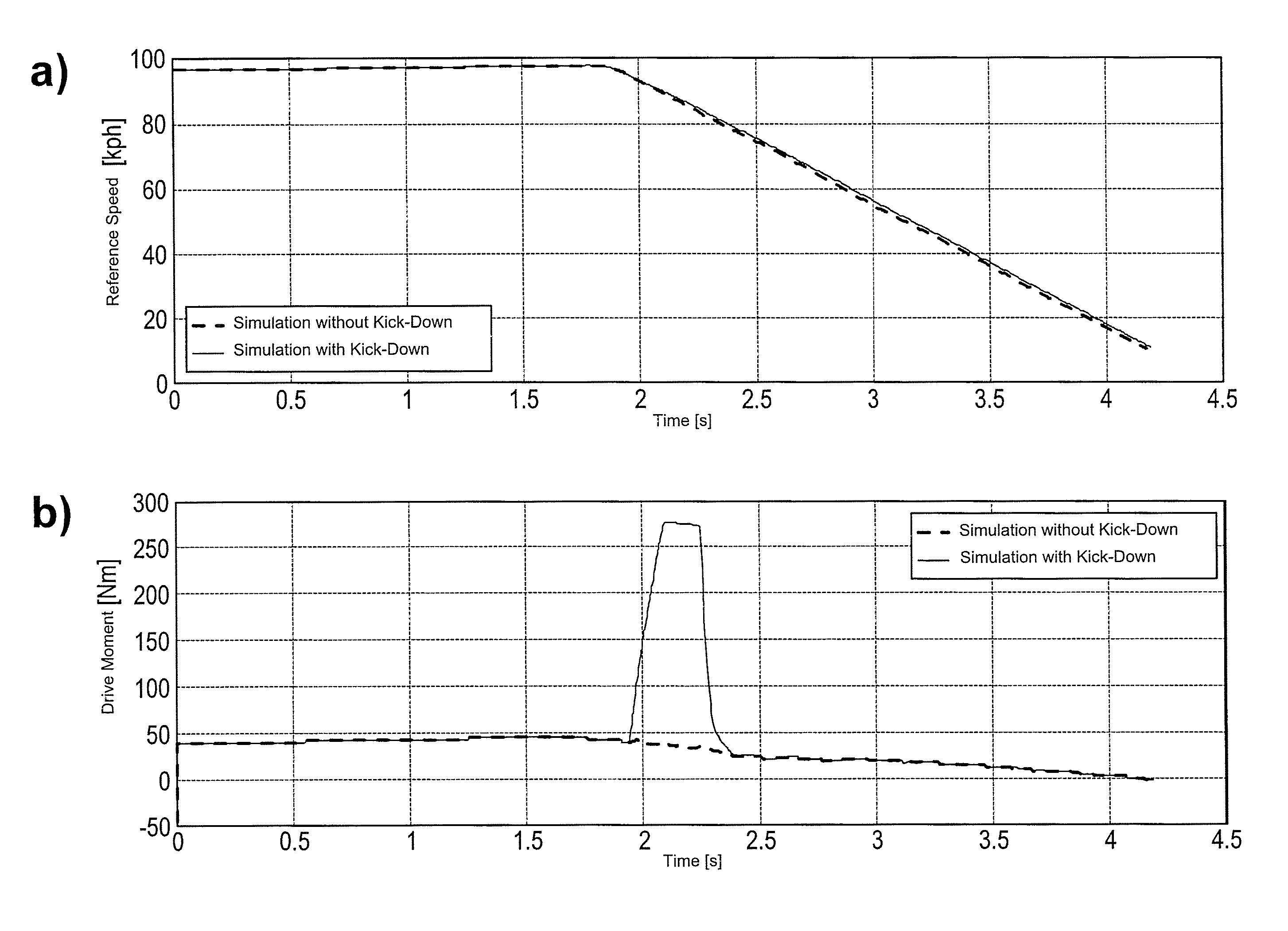
[0096]In contrast thereto, the present invention takes a new path. This is the surprising advantage of the invention being discussed here, that is, that compensation for the dynamic transference of an axle load can be obtained by an alteration, preferably a brief increase in, the drive moment, in particular by means of an accelerator stroke.
[0097]If the motor vehicle pitches because of a full braking action for example and in consequence the wheel contact force at the front axle initially rises massively due to the forwardly directed dynamic transfer of the axle load, this leads to a simultaneous reduction in the load on the rear axle. Consequently, the rear tires lose contact force and the lateral cornering force decreases rapidly. This pitching effect is exactly reversed in the event of extreme acceleration of the vehicle. The vehicle rears up at the front and goes down on its knees at the back. The rear axle is more heavily loaded thereby and the load on the front axle is reduced. The present invention involving a method of deliberately affecting the dynamic transfer of the axle load that is proposed here for the first time takes positive advantage of this known pitching behavior of a vehicle that occurs when the brakes are fully applied or when full power is applied for the purposes of rapid acceleration, but without actually producing acceleration of the vehicle thereby.
[0098]It is proposed for the first time that a brief increase of the drive moment be applied e.g. at the point of applying the brakes in the event of a braking action or at the critical swerving point in the event of driving to the extreme in a curve, so that the reaction of the vehicle will actually be a proportionate righting of the motor vehicle, the attainment of compensation for the dynamic transfer of the axle load and an increase in or adaptation of the normal force and / or the lateral force of the tire that is transmissible effectively to the front and / or rear axle is obtained whilst nevertheless any acceleration of the vehicle reliably fails to materialize.
[0099]Thus, a surprising swerve during a full braking action can be avoided. Furthermore, surprising oversteering can be reduced. The danger of a rolling movement is reduced and thus finally, the danger of skidding is diminished.
[0100]Hereby, the invention takes advantage for the first time of the effect that the time constant between the increase in the drive moment and the reaction of the vehicle as such is large. Thus then, the vehicle only reacts slowly to the demanded drive moment due to its inertia. Consequently, although the drive moment can in fact influence the drive train up to the drive wheels, they will still not be accelerated however. In addition, when braking, the drive torque is thereby up against the several times higher braking force so that acceleration of the vehicle is out of the question, but an increase of the wheel contact force at the rear axle can be reliably obtained.
[0101]Initially hereby, reaction forces are produced which entail at least a slight righting of the motor vehicle, but no acceleration of the motor vehicle can be objectively detected however. Due to the at least partial straightening of the motor vehicle i.e. due to the counter-balancing of the dynamic transfer of the axle load from its extremely forward position beforehand to one in which the axle load distribution is now virtually balanced, care has in turn been taken in an advantageous manner to ensure that sufficient contact force for the rear wheels is attainable so that substantially higher braking and lateral forces can be transmitted than was the case in the critical driving situation occurring a few fractions of a second before.

Problems solved by technology

The tires on the front axle are thereby extremely heavily loaded and thus are possibly no longer following linear operating points.
Control of the vehicle as desired by the driver is then frequently no longer possible without systems for regulating the dynamics of the vehicle's movement.
Although the successes and improvements in regard to the dynamic transference of the axle load that can be attained thereby are indeed promising and have also proved satisfactory in practice, they are still inadequate for fully controlling a motor vehicle in every driving situation.

Method used


Image

  • Systems and methods for compensation for a dynamic axle load transfer
  • Systems and methods for compensation for a dynamic axle load transfer
  • Systems and methods for compensation for a dynamic axle load transfer

Examples


Embodiment Construction

[0044]The following detailed description of the invention is merely exemplary in nature and is not intended to limit the invention or the application and uses of the invention. Furthermore, there is no intention to be bound by any theory presented in the preceding background of the invention or the following detailed description of the invention.

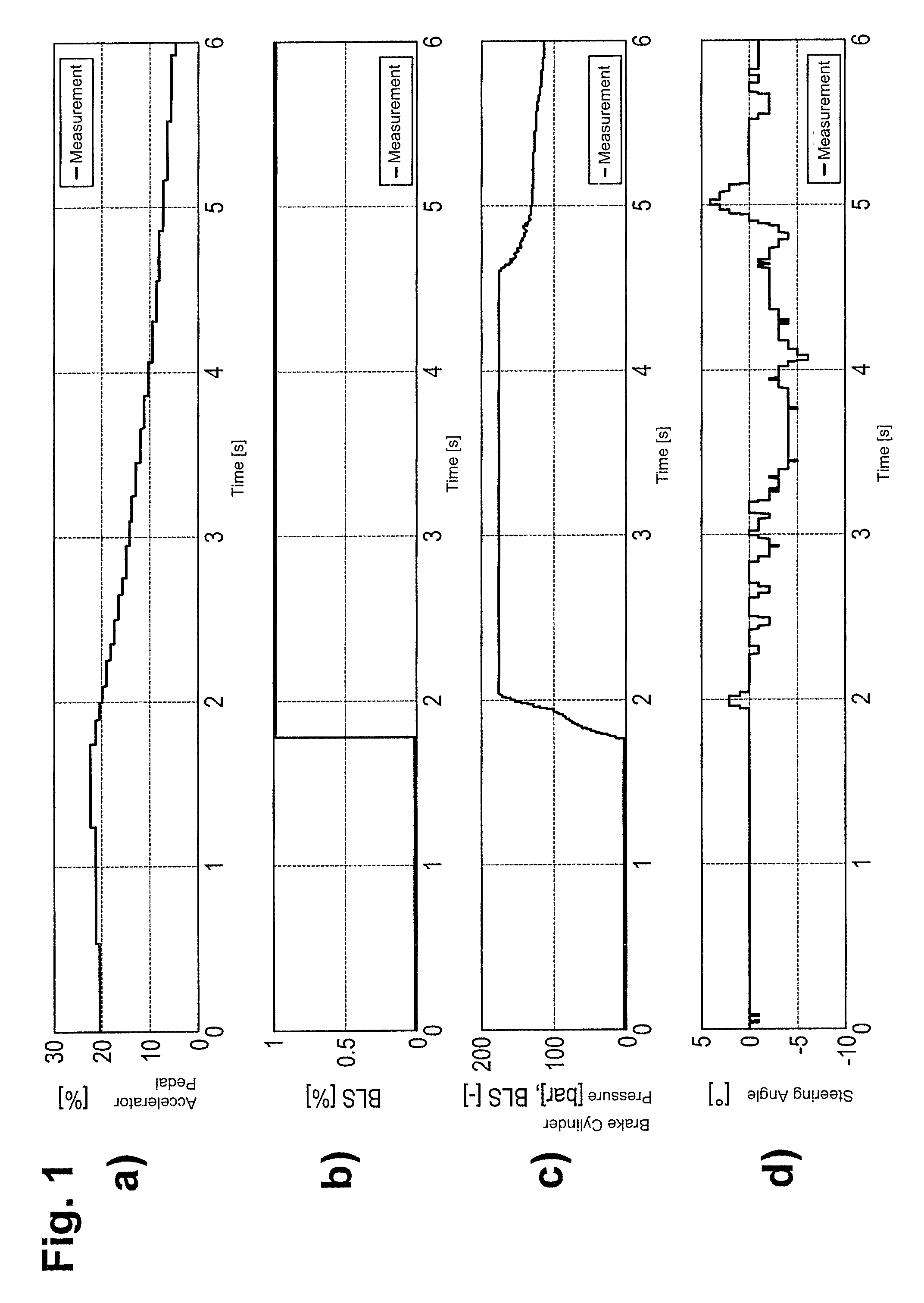
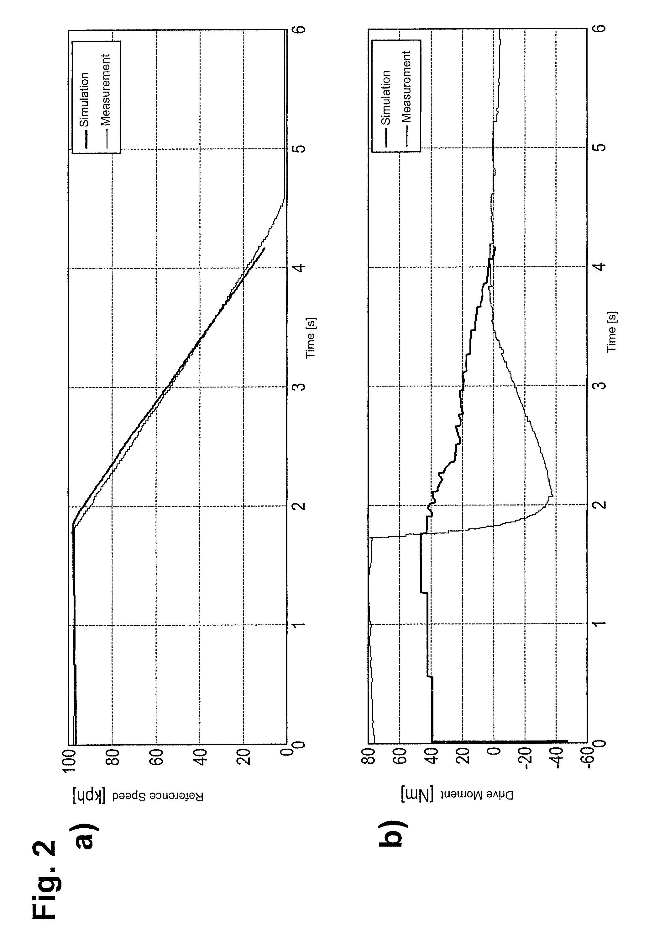
[0045]A first exemplary driving situation, which proceeds on the basis of traveling in a straight line at 100 km / h and then a suddenly-implemented full braking action, is illustrated in FIGS. 1 to 5.

[0046]A dynamic transfer of the axle load occurs when applying full braking. It depends upon, among other things, the height of the motor vehicle's center of gravity. The dynamic transfer of the axle load causes an alteration in the wheel contact forces. The ratio between the wheel braking torque and the drive moment is, e.g., approx. 10:1 to 20:1. If, during a full braking action with blocking wheels, one now increases the drive moment for a sho...


PUM


Abstract

The present invention proposes an improved method for at least partially compensating for the dynamic transfer of an axle load when part of a motor vehicle load dips over at least one front wheel. A demand for a drive moment is applied and thus a time-limited virtually maximum drive moment is produced for the purposes of compensating for the transfer of the axle load. Moreover, for the first time, the present invention proposes a microprocessor and also a control device for carrying out this method in accordance with the invention. Furthermore, a motor vehicle drive is indicated which is equipped with such a control device or such a microprocessor. Finally, software is designated for carrying out the method. A motor vehicle is presented which is equipped with such a control device or such a microprocessor for the execution of the software for carrying out the method in accordance with the invention.

Description

CROSS-REFERENCE TO RELATED APPLICATIONS[0001]This application is a U.S. National-Stage entry under 35 U.S.C. §371 based on International Application No. PCT / EP2005 / 005080, filed May 6, 2005, which was published under PCT Article 21(2) and which claims priority to German Application No. DE 10 2004 022 892.2, filed May 10, 2004.FIELD OF THE INVENTION[0002]The present invention relates to systems and methods for at least partially compensating for the dynamic transfer of an axle load in a motor vehicle.BACKGROUND[0003]In practice, it is known that the dynamic transfer of an axle load due to the acceleration or deceleration of a motor vehicle causes a change in the opposite sense in the momentary normal force on the front and rear axle. Because of the dependency of the tire cornering force on the normal force, the distribution of the lateral force between the front and the rear axle changes whereby a moment turning into the curve develops during deceleration and a moment turning out of ...

Claims


Application Information

Patent Timeline
Patent Type & Authority Patents(United States)
IPC IPC(8): G06F19/00B62D37/00B60K28/10B60T8/1766B60W10/04B60W10/18B60W10/22B60W30/02
CPCB60T8/1766B60W30/045B60W10/18B60W10/22B60W10/04B60T2230/06B60T2270/303
Inventor STEIMEL, CHRISTOPH
Owner GM GLOBAL TECH OPERATIONS LLC
Learn More