Supporting device with ball socket, column socket and plane combined in mass center measurement

A technology of support device and plane phase, applied in the field of support structure, can solve the problems of large friction force, poor centering position accuracy, difficult automatic adjustment of sensors, etc. in the spherical plane support method, so as to shorten the centering process time and improve the measurement accuracy. Accuracy, effect of mutual constraint reduction

Active Publication Date: 2014-09-10
HARBIN INST OF TECH
View PDF5 Cites 11 Cited by
  • Summary
  • Abstract
  • Description
  • Claims
  • Application Information

AI Technical Summary

Problems solved by technology

[0018] The present invention aims to solve the problems that the existing ball-ball-socket support method for centroid measurement is difficult for the sensor to automatically adjust to the center of the bearing point, the accuracy of the centering position is poor, and the ball plane support method has a large guide friction force, and further provides A support device combining ball-socket, column-socket and plane in centroid measurement

Method used


Image

  • Supporting device with ball socket, column socket and plane combined in mass center measurement
  • Supporting device with ball socket, column socket and plane combined in mass center measurement
  • Supporting device with ball socket, column socket and plane combined in mass center measurement

Examples


specific Embodiment approach 1

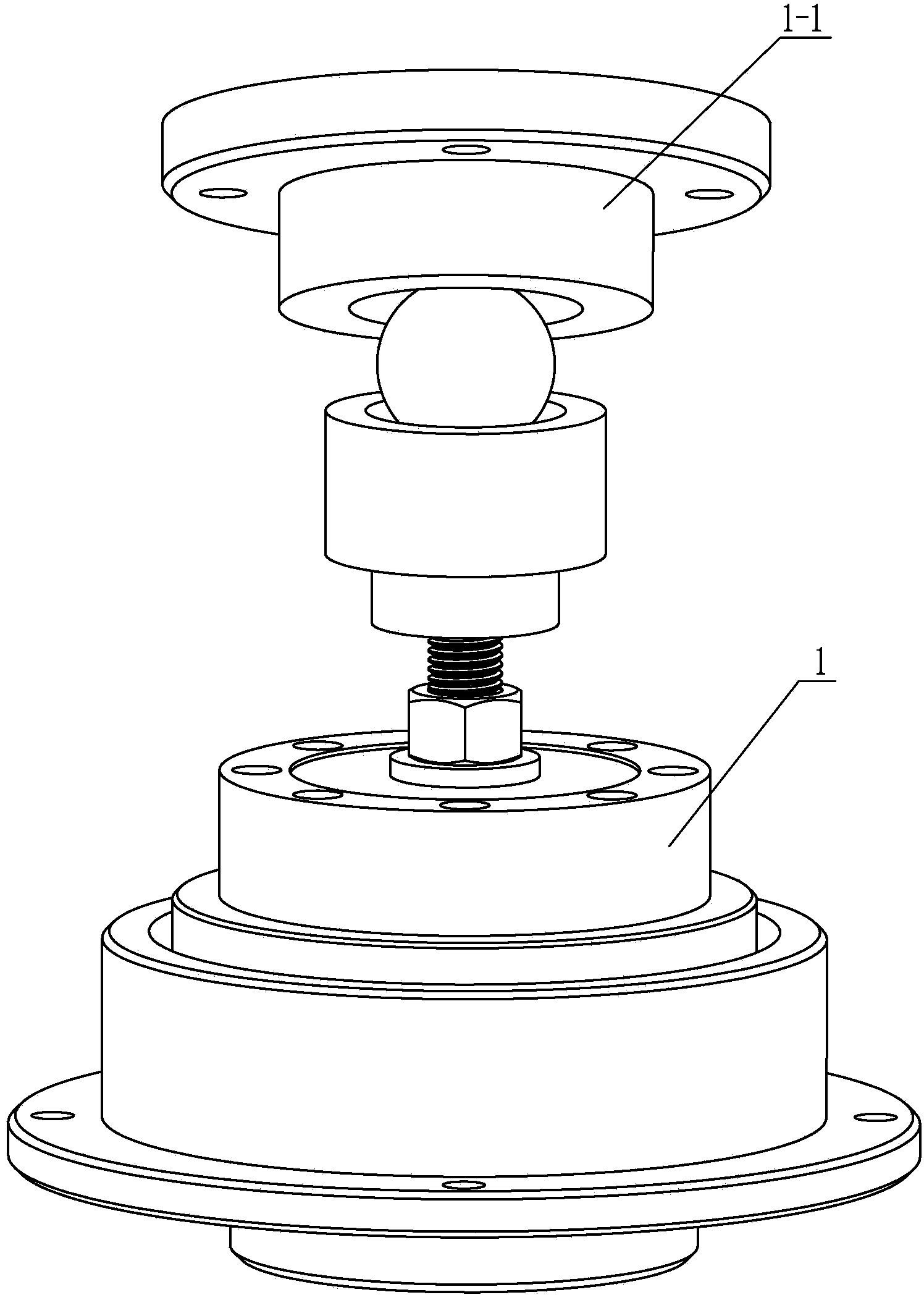
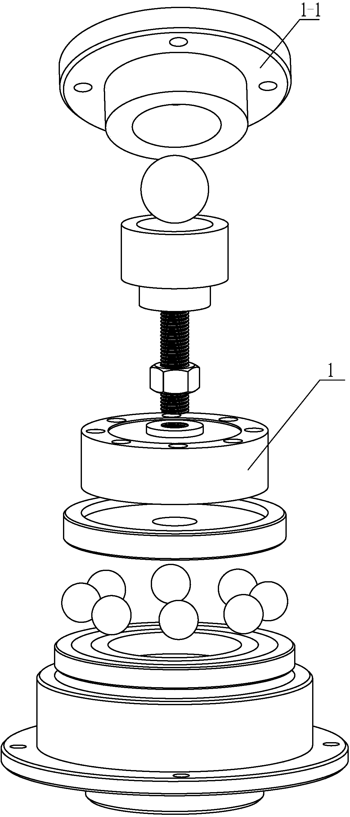
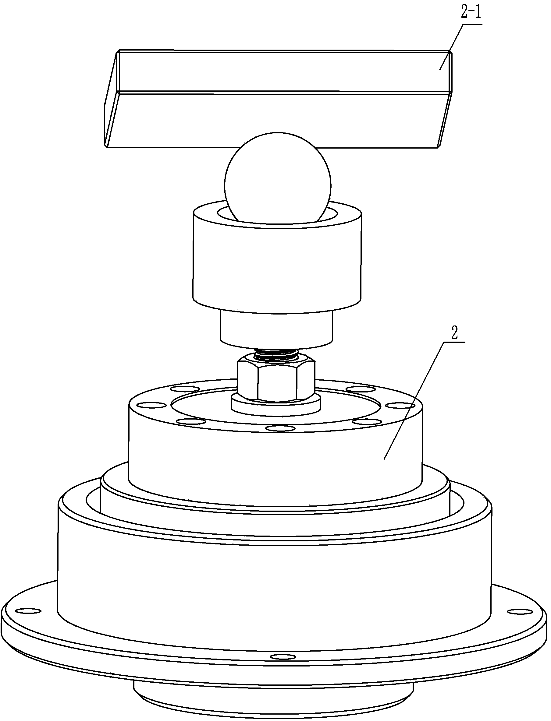
[0024] Specific implementation mode one: combine Figure 4-Figure 6 Illustrate, the support device that combines ball socket, column socket, and plane in the center of mass measurement of this embodiment includes ball socket support structure 1, spherical plane support structure 2 and measurement pedestal 3; Said support device also includes column socket support structure 4, The ball-socket support structure 1, the column-socket support structure 4 and the spherical plane support structure 2 are arranged in an isosceles triangle on the measurement pedestal 3; the column-socket support structure 4 includes a column-socket plate 4-1, a steel ball 4-2, a ball Seat 4-3, load-bearing sensor 4-4, load-bearing sensor tray 4-5 and base 4-7, load-bearing sensor 4-4 is installed on the load-bearing sensor tray 4-5, and load-bearing sensor tray 4-5 is rotatably installed on base 4- 7, the base 4-7 is installed on the measuring pedestal 3, the ball seat 4-3 is detachably installed on the...

specific Embodiment approach 2

[0026] Embodiment 2: The measurement base 3 in this embodiment is a circular base. This setting meets the design requirements and the actual centroid measurement needs. Others are the same as in the first embodiment.

specific Embodiment approach 3

[0027] Specific implementation mode three: combination Figure 6 To illustrate, the measurement base 3 in this embodiment is a rectangular base. This setting meets the design requirements and the actual centroid measurement needs. Others are the same as in the first embodiment.


PUM


Abstract

The invention provides a supporting device with a ball socket, a column socket and a plane combined in mass center measurement and relates to a supporting structure. The problems that a sensor adopted in an existing mass center measurement ball-ball socket supporting method can not be automatically adjusted to the position aligned with a bearing point, accuracy of the alignment position is poor, and guide friction force is large in a ball plane supporting method can be solved. The supporting device comprises a ball socket supporting structure, a ball plane supporting structure and a measurement pedestal and further comprises a column socket supporting structure. The column socket supporting structure comprises a column socket board, a steel ball, a ball base, a bearing sensor, a bearing sensor tray and a base. The bearing sensor is installed on the bearing sensor tray. The bearing sensor tray is rotationally installed on the base. The base is installed on the measurement pedestal. The ball base is detachably installed on the bearing sensor. The steel ball is placed in the middle of the upper surface of the ball base. The horizontally-arranged column socket board is placed on the upper portion of the steel ball. The supporting device is used for large-size aircraft mass center measurement.

Description

technical field [0001] The invention relates to a support structure, in particular to a support structure of large-scale aircraft centroid measurement equipment. Background technique [0002] The support method of large-scale aircraft centroid measurement equipment and the problem of lateral force have always existed, which affect the measurement accuracy. From the basic principle of the multi-point method, it can be known that the output value of the sensor and the measurement value of the position of the force point of the sensor directly affect the measurement result of the mass center of mass, so how to ensure the accuracy of the output value of the sensor and the measurement value of the position of the force point of the sensor center has become an important issue for improvement. The key factor for the measurement accuracy of the centroid of mass measuring platform. The supporting structure of the sensor is a key factor affecting the output characteristics of the sen...

Claims


Application Information

Patent Timeline
Patent Type & Authority Applications(China)
IPC IPC(8): G01M1/02
Inventor 张晓琳唐文彦梁秀杰王军张烈山刘万村
Owner HARBIN INST OF TECH
Why Eureka
Try Eureka