
Micro total analysis system

a total analysis and micro-computer technology, applied in the direction of ratio control, flow control, shaking/oscillating/vibrating mixer, etc., can solve the problems of difficult to stabilize the mixing ratio, the flow rate is varied from the target value, and the mixing ratio can be controlled accurately. , to achieve the effect of stable mixing ratio of two fluids and control of the mixing ratio

Active Publication Date: 2010-06-01
KONICA MINOLTA MEDICAL & GRAPHICS INC
View PDF11 Cites 13 Cited by
  • Summary
  • Abstract
  • Description
  • Claims
  • Application Information

AI Technical Summary

Benefits of technology

[0010]The present invention was developed in view of the above situation and is intended to provide a micro total analysis system for mixing two kinds of fluids at a mixing ratio of m:n without changing drive voltages of micro-pumps for feeding the respective fluids and controlling accurately the mixing ratio. It is an object of this invention that in this system, even if the mixing ratio is widely different from 1:1, a stable mixing ratio of two fluids can be ensured.

Problems solved by technology

However, when the mixing ratio is high, it is necessary to lower the drive voltage of one micro-pump considerably, relative to the other, so that a problem arises that the mixing ratio can be hardly stabilized due to the pumping force of the other one.
Even if target values of the flow rates are determined and drive voltages according to them are supplied to the micro-pumps, a problem arises that the flow rates are varied from the target values due to changes in the flow path resistances.
When the flow path is additionally extended downward from the joining part of the flow paths like this case, the flow rates are varied with time due to changes in the flow path resistance of the downstream flow path and liquid feeding pressure, so that it is more difficult to stabilize the mixing ratio.

Method used


Image

  • Micro total analysis system
  • Micro total analysis system
  • Micro total analysis system

Examples


Embodiment Construction

[0022]The above object can be accomplished by the following configurations.

The micro total analysis system of the invention includes,

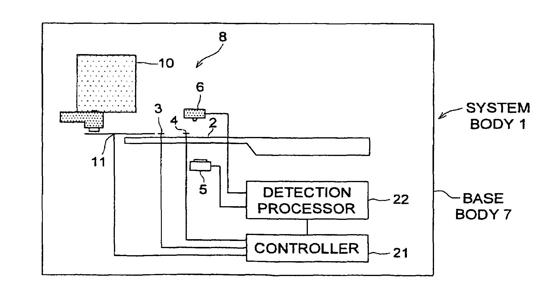
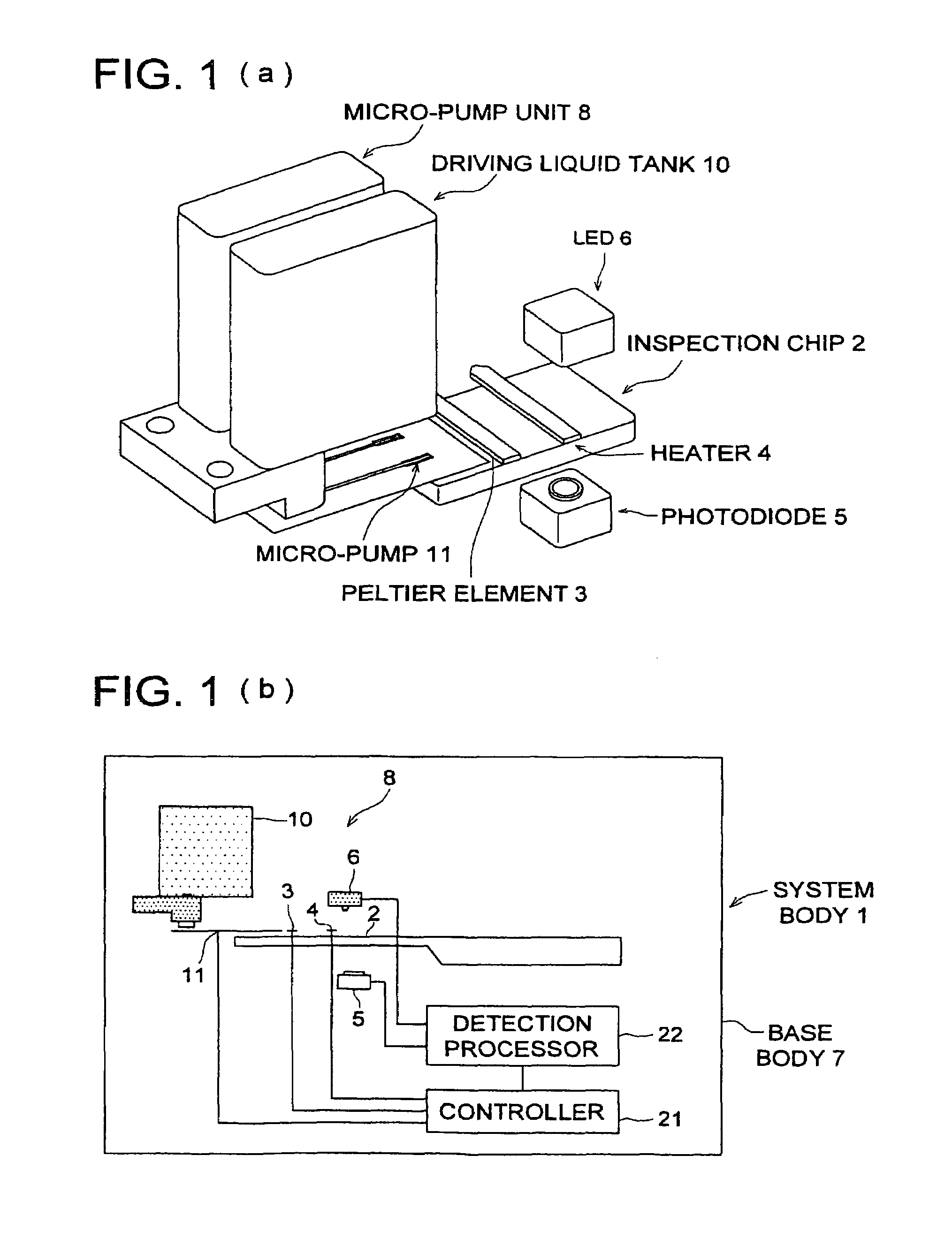
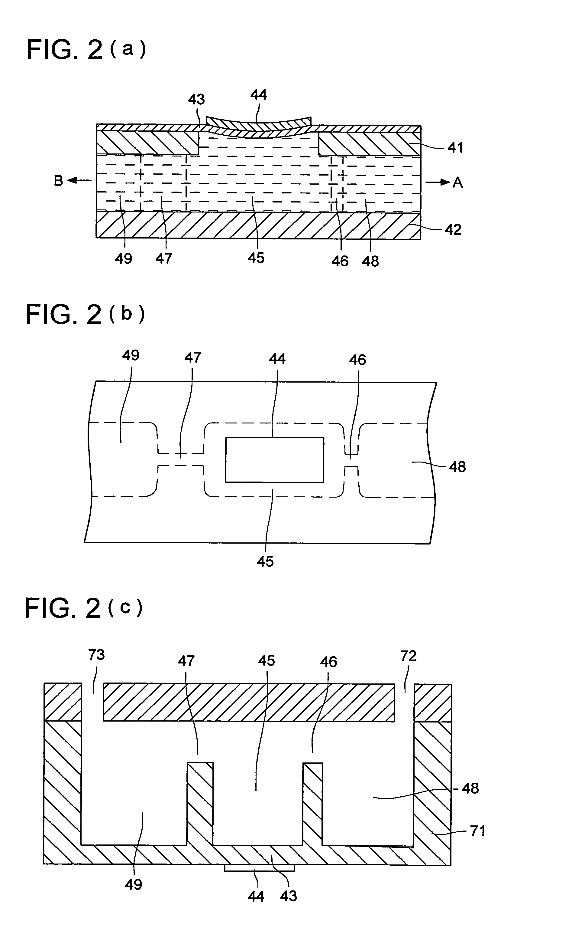
[0023]an inspection chip having at least;[0024]a pump connection having a flow path opening for communicating with a micro-pump;[0025]a flow path in which fluid flows; and[0026]a fluid mixing section on which two or more fluids are joined and mixed,

and the system further includes

[0027]a system body having at least;[0028]a base body;[0029]a chip connection positioned in the base body and having a flow path opening for communicating with the inspection chip;[0030]a micro-pump unit having a plurality of micro-pumps of substantially same shape;[0031]a detection processor;[0032]a controller for controlling at least functions of the micro-pump unit and the detection processor,

[0033]and when a mixing ratio of the two fluids joining at the fluid mixing section is approximately a ratio of m to n (the ratio is not 1 to 1), a joining amount ratio is adjusted whil...


PUM

PropertyMeasurementUnit
thicknessaaaaaaaaaa
thicknessaaaaaaaaaa
lengthaaaaaaaaaa

Abstract

A system including an inspection chip equipped with at least a pump connection having a flow path opening for interconnecting to a micro-pump, a flow path through which a fluid flows, and a fluid mixing section for joining and mixing two or more fluids, and including a system body equipped with at least a base body, a chip connection having a flow path opening for interconnecting to the inspection chip, a micro-pump unit in the base body including micro-pumps in substantially the same shape, a detection processor and a controller for controlling at least the functions of the micro-pump unit and the detection processor, and the joining amount ratio is adjusted to set the mixing ratio of two fluids to be joined in the fluid mixing section to be approximately m:n (not 1:1) by making the drive voltages of the micro-pumps substantially equal to each other.

Description

[0001]This application is based on Japanese Patent Application No. 2005-086681 filed on Mar. 24, 2005 in Japanese Patent Office, the entire content of which is hereby incorporated by reference.BACKGROUND OF THE INVENTION[0002]In recent years, due to the use of micro-machine technology and microscopic processing technology, systems are being developed in which devices and means (for example pumps, valves, flow paths, sensors and the like) for performing conventional sample preparation, chemical analysis, chemical synthesis and the like are caused to be ultra-fine and integrated on a single chip (Patent Document 1). These systems are called μ-TAS (Micro Total Analysis System), bioreactor, lab-on-chips, and biochips, and much is expected of their application in the fields of medical testing and diagnosis, environmental measurement and agricultural manufacturing. In reality, as seen in gene screening, in the case where complicated steps, skilful operations, and machinery operations are ...

Claims


Application Information

Patent Timeline
Patent Type & Authority Patents(United States)
IPC IPC(8): B01L3/02G01N1/00G01N15/06E03B1/00G01N1/14
CPCB01F11/0071B01F13/0059B01F15/042B01L3/50273B01L3/502746F04B43/046G05D7/0694G05D11/132B01L2300/0867Y10T436/25B01L2400/0487B01L2400/084B01L2400/0439Y10T137/0318Y10T137/0324B01F31/65B01F33/30B01F35/8311
Inventor HIGASHINO, KUSUNOKINAKAJIMA, AKIHISASANDO, YASUHIRO
Owner KONICA MINOLTA MEDICAL & GRAPHICS INC
Learn More