Method of limiting communication access between wireless LAN terminals

a technology of wireless lan terminals and communication access, which is applied in the direction of frequency-division multiplex, wireless commuication services, instruments, etc., can solve the problems of consuming the entire wireless band, stealing the communication between wireless lan terminals, and not having a lot of money to spend on constructing a network of their own

a technology of wireless lan terminals and communication access, which is applied in the direction of frequency-division multiplex, wireless commuication services, instruments, etc., can solve the problems of consuming the entire wireless band, stealing the communication between wireless lan terminals, and not having a lot of money to spend on constructing a network of their own

US7729324B2Active Publication Date: 2010-06-01NEC CORP

Image

  • Method of limiting communication access between wireless LAN terminals
  • Method of limiting communication access between wireless LAN terminals
  • Method of limiting communication access between wireless LAN terminals

Examples


Embodiment Construction

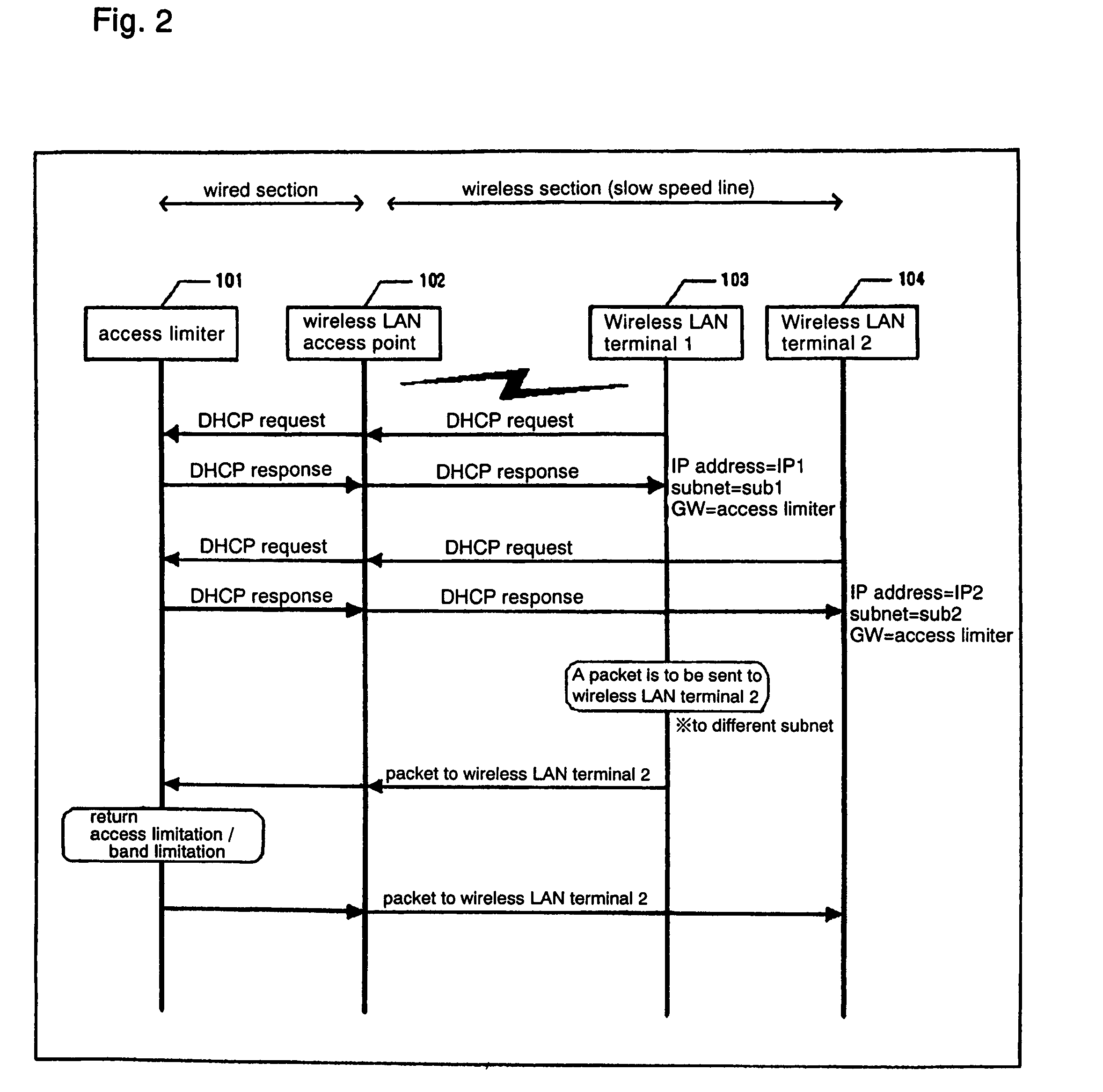
[0057]FIG. 2 shows a sequence of operation of a wireless LAN according to the present invention.

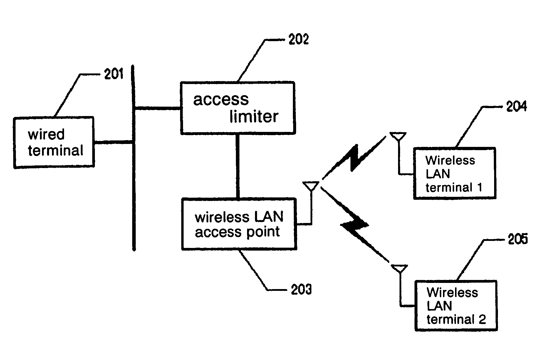
[0058]As shown in FIG. 2, the wireless LAN has access limiter 101 which is a device for achieving features of the present invention. Access limiter 101 has a routing function for returning packets sent between wireless LAN terminals, an access limiting function, and a DHCP (Dynamic Host. Configuration Protocol) server function which is an automatic address resolution function for IP addresses. Wireless LAN access point 102 operates to bridge between a wireless LAN and a wired LAN. Wireless LAN terminals 103, 104 communicate with wireless LAN access point 102.

[0059]When wireless LAN terminal 1 (103) is turned on, it sends a DHCP request for automatically resolving its own IP address to wireless LAN access point 102. Since wireless LAN access point 102 operates as a simple wired / wireless terminal bridge, it transfers the received DHCP request to access limiter 101. Access limiter 101 with t...


PUM


Abstract

Different subnets are allocated to respective wireless LAN terminals. It is assumed that when the setting of IP addresses is completed, a packet is to be sent from wireless LAN terminal 1 to wireless LAN terminal 2. Since the different subnets are allocated to respective wireless LAN terminals 1, 2, wireless LAN terminals 1, 2 are unable to communicate directly with each other. Wireless LAN terminal 1 sends a packet destined for wireless LAN terminal 2 to a default gateway (=access limiter). Since the packet received by the access limiter is destined for wireless LAN terminal 2, the access limiter transfers the packet to wireless LAN terminal 2.

Description

BACKGROUND OF THE INVENTION[0001]1. Field of the Invention[0002]The present invention relates to a method of limiting communication access between wireless LAN terminals.[0003]2. Description of the Related Art[0004]Some conventional inter-LAN repeaters for use in wireless LAN access point installations for regenerating signals between wired LANs and wireless LANs are capable of dispensing with unwanted repeating operation for unstudied stations in the wireless LANs thereby to greatly reduce the load on transmission paths in the wireless LANs which have a low transmission rate (see, for example, Patent Document 1 below).[0005]There is known a wireless LAN system in which an access point as a control terminal device receives a frame destined outside a cell and makes a response representative of a reception success or a reception failure for efficient communications with a wireless terminal device in another cell or a wired terminal device connected to a wired transmission path (see, f...

Claims


Application Information

Patent Timeline
01 Jun 2010
Publication
US7729324B2
IPC
H04W4/00; H04L12/28
CPC
H04L29/12028; H04L29/12933; H04L61/103; H04L61/2015; H04L61/6068; H04W48/02; H04L12/14; H04W92/18
Inventors
KACHI, SEIJI