Wear assembly

a technology for wearing parts and parts, applied in soil shifting machines/dredgers, constructions, etc., can solve the problems of wear parts that are commonly subjected to harsh conditions and heavy loading wear parts that need to be replaced, etc., to achieve enhanced stability, resist vertical and side loads, and maximize the available stabilizing surfaces

Active Publication Date: 2010-06-08
ESCO GRP LLC
View PDF38 Cites 67 Cited by
  • Summary
  • Abstract
  • Description
  • Claims
  • Application Information

AI Technical Summary

Benefits of technology

[0005]The present invention pertains to an improved wear assembly for securing wear members to excavating equipment for enhanced stability, strength, durability, penetration, safety, and ease of replacement.
[0006]In accordance with one aspect of the invention, the base and wear member define a nose and socket, which are formed with complementary stabilizing surfaces extending substantially parallel to the longitudinal axis of the assembly to provide a stronger and more stable construction. One or more of the stabilizing surfaces are formed generally along central portions of the nose and socket, and away from the outer edges of these components. As a result, the high loads anticipated during use are primarily carried by the more robust portion of the nose, and not on the extreme bending fibers, for a stronger and longer lasting base structure. This construction further reduces the formation of high stress concentrations along the components.

Problems solved by technology

These kinds of wear parts are commonly subjected to harsh conditions and heavy loading.
Accordingly, the wear members wear out over a period of time and need to be replaced.

Method used


Image

  • Wear assembly
  • Wear assembly
  • Wear assembly

Examples


Embodiment Construction

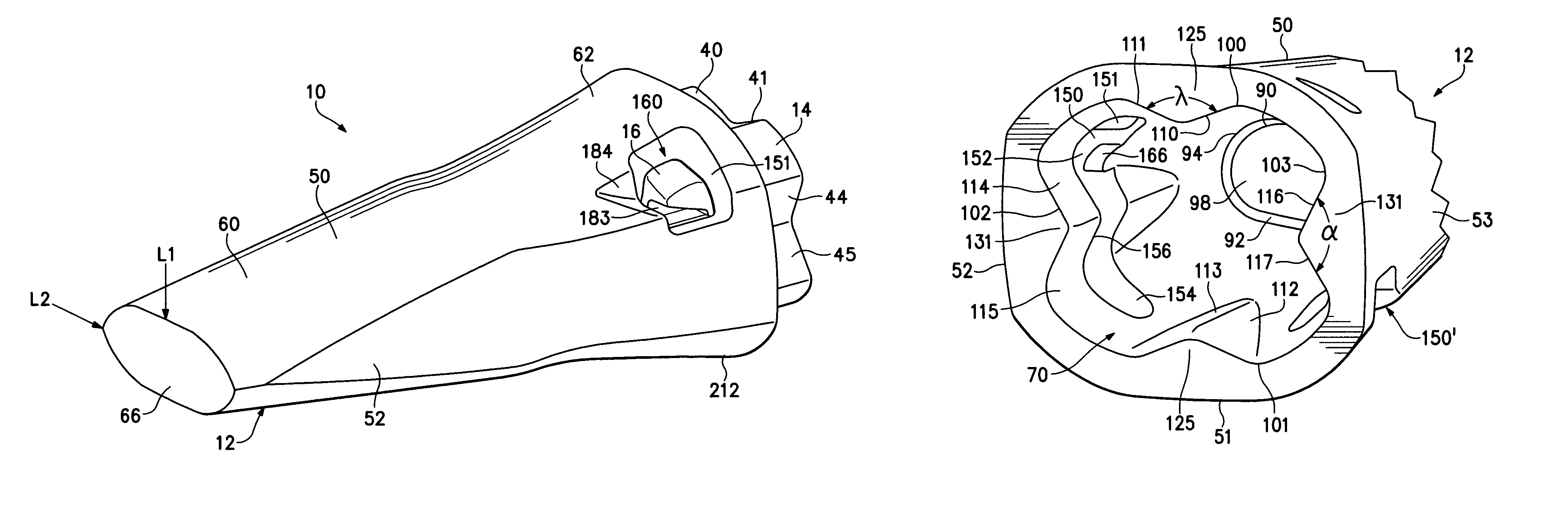
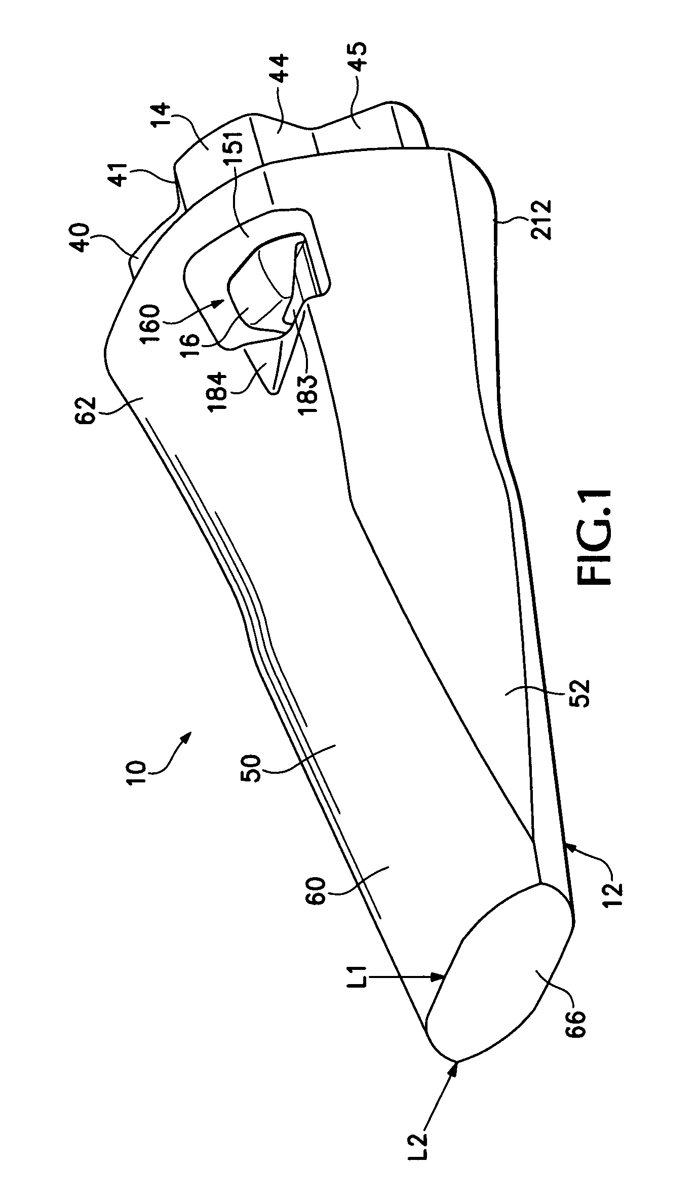
[0025]The present invention pertains to a wear assembly 10 for releasably attaching a wear member 12 to excavating equipment. In this application, wear member 12 is described in terms of a point for an excavating tooth that is attached to a lip 13 of an excavating bucket. However, the wear member could be in the form of other kinds of products (e.g., shrouds) or attached to other equipment (e.g., dredge cutterheads). Moreover, relative terms such as forward, rearward, up, down, vertical or horizontal are used for convenience of explanation with reference to FIG. 1; other orientations are possible.

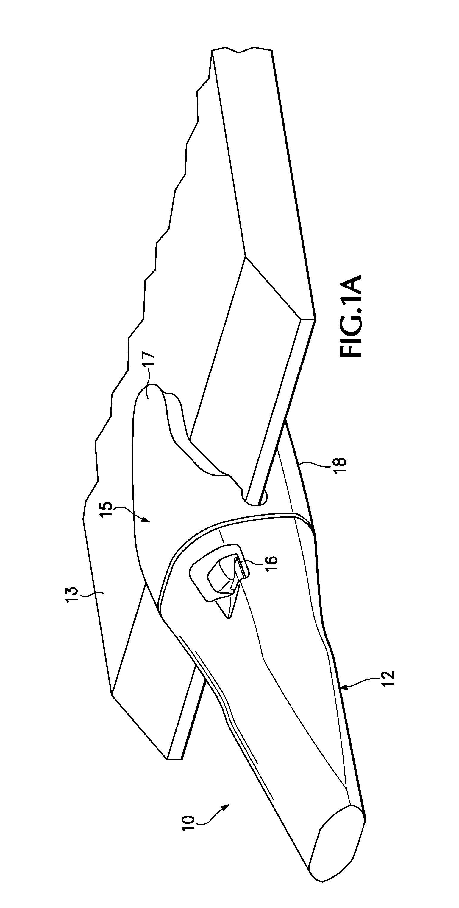
[0026]In one embodiment (FIGS. 1 and 1A), point 12 is adapted to fit on nose 14 fixed to a bucket lip 13 or other excavating equipment (not shown). In this embodiment, the nose is the front part of a base 15 that is fixed to an excavating bucket. The rear mounting end of the base (not shown in FIG. 1) can be fixed to the bucket lip 13 in a number of ways. For example, the nose can be formed...


PUM


Abstract

A wear assembly for securing a wear member to excavating equipment that includes a base having a nose and a wear member having a socket. The nose and socket are each provided with one or more complementary stabilizing surfaces in central portions thereof.

Description

FIELD OF THE INVENTION[0001]The present invention pertains to a wear assembly for securing a wear member to excavating equipment.BACKGROUND OF THE INVENTION[0002]Wear parts are commonly attached along the front edge of excavating equipment, such as excavating buckets or cutterheads, to protect the equipment from wear and to enhance the digging operation. The wear parts may include excavating teeth, shrouds, etc. Such wear parts typically include a base, a wear member and a lock to releasably hold the wear member to the base.[0003]In regard to excavating teeth, the base includes a nose which is fixed to the front edge of the excavating equipment (e.g., a lip of a bucket). The nose may be formed as an integral part of the front edge or as part of one or more adapters that are fixed to the front edge by welding or mechanical attachment. A point is fit over the nose. The point narrows to a front digging edge for penetrating and breaking up the ground. The assembled nose and point cooper...

Claims


Application Information

Patent Timeline
Patent Type & Authority Patents(United States)
IPC IPC(8): E02F9/28
CPCE02F9/28E02F9/2883E02F9/2833E02F9/2825
Inventor CARPENTER, CHRISTOPHER M.
Owner ESCO GRP LLC
Why Eureka
Try Eureka