Refrigerating storage cabinet

a technology for refrigerating storage cabinets and storage cabinets, which is applied in the field of refrigerating storage cabinets, can solve the problems of inconvenience and complication, and achieve the effects of preventing the formation of a large amount of frost, reducing energy consumption, and reducing the cost of production

Inactive Publication Date: 2010-06-08
HOSHIZAKI ELECTRIC CO LTD
View PDF26 Cites 8 Cited by
  • Summary
  • Abstract
  • Description
  • Claims
  • Application Information

AI Technical Summary

Benefits of technology

[0031]The performance of the compressor is controlled so that the corresponding physical amount is reduced following the control-cooling characteristic during the operation of the compressor in control-cooling. When the control-cooling characteristic is set at a gentle gradient, the cooling can be carried out while the compressor is in low performance operation, namely, while energy savings are achieved. On the other hand, when the control-cooling characteristic is suitably set at a lower limit temperature, the operation of the compressor can reliably be stopped, whereby a defrosting operation is performed in the evaporator. Accordingly, a large amount of frost can be prevented.
[0047]When the load or the like raises the internal temperature, which was currently being decreased from the set temperature to the lower limit temperature, it takes a large amount of time to drop the internal temperature to the lower limit temperature thereafter. Accordingly, the compressor is continuously operated for a long period of time. In view of this, the performance of the compressor is increased when the internal temperature starts to rise, so that the internal temperature falls again to the lower limit temperature. Consequently, the compressor can be reliably stopped at a suitable time.

Problems solved by technology

For example, refrigeration starting from a high internal temperature, such as 20° C., is substantially limited to an initial operation after installation, re-operation several times after turning the power off for maintenance, several minutes of door opening to insert food materials, or the accommodation of hot food.
As a result, there is a problem of inconvenience and complication, such as the problem in which the places where and the times when a test should be conducted are limited.

Method used


Image

  • Refrigerating storage cabinet
  • Refrigerating storage cabinet
  • Refrigerating storage cabinet

Examples


embodiment 1

[0075]Embodiment 1 will be described with reference to FIGS. 1 to 10.

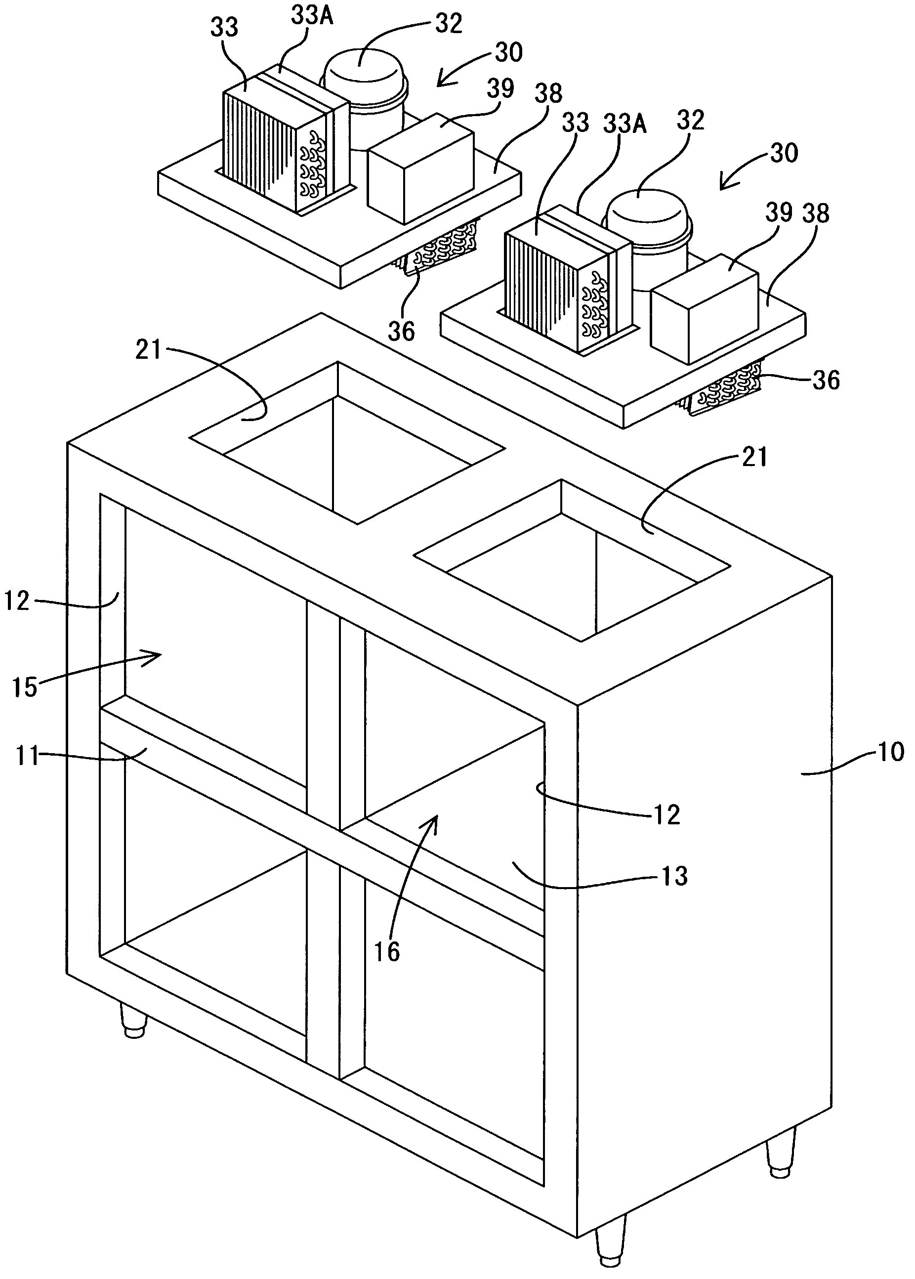
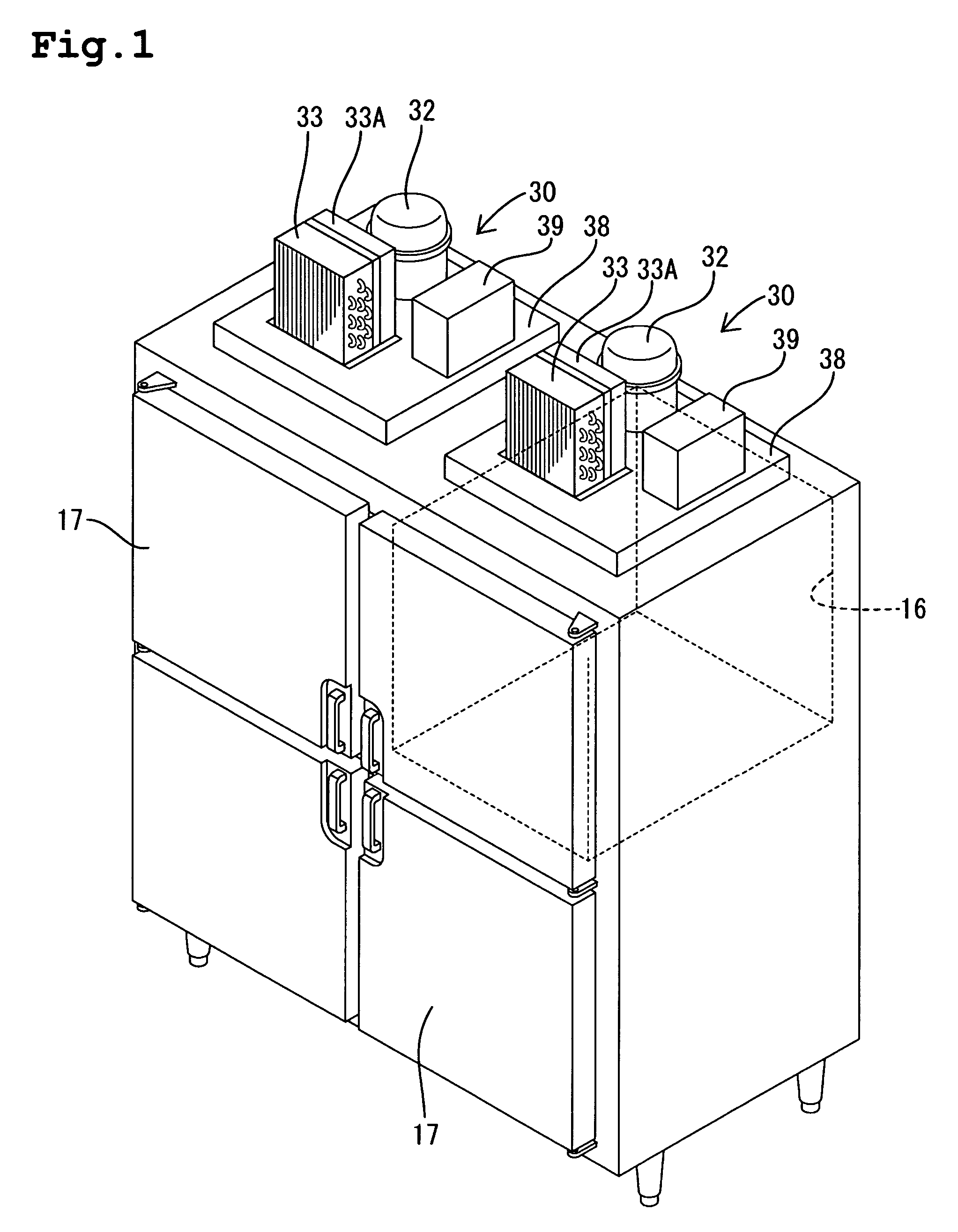
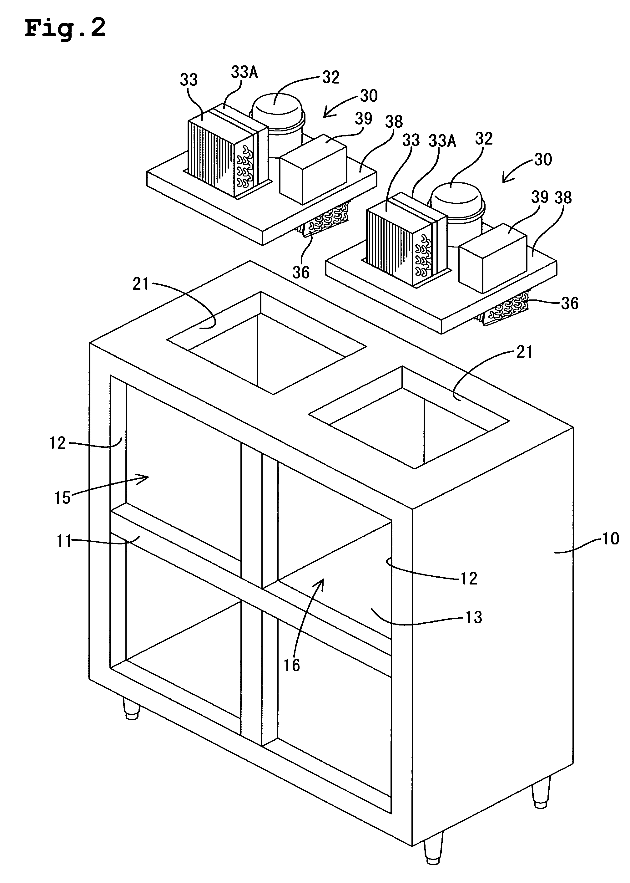
[0076]The refrigerator-freezer is a four-door type and is provided with a body 10 comprising a heat insulating housing having an open front, as shown in FIGS. 1 and 2. A cruciform partition frame 11 partitions the open front into four access openings 12. Heat insulating walls 13 partition substantially a quarter of the inner space, corresponding to an upper right access opening 12 as viewed from the front, thereby forming a freezing compartment 16. The remaining three quarters of the inner space serve as a refrigerating compartment 15. Heat insulating doors 17 are pivotally mounted so as to respectively close and open the access openings 12.

[0077]An equipment compartment is defined on the top of the body 10 by a panel 19 (see FIG. 4) erected around the top of the body. Square openings 21, which have the same size, are formed in the top of the body 10, which serves as a bottom of the equipment compartment 20, so as ...

embodiment 2

[0134]Embodiment 2 of the present invention will be described with reference to FIGS. 11 to 13.

[0135]In embodiment 2, an ideal temperature curve in pull down cooling is formed by the curve xp1 of a quadratic function involving a physical amount and time, as shown in FIG. 11. When a constant speed compressor is used, the temperature drop characteristic in pull down cooling is generally represented as a quadratic function curve. On the other hand, this temperature drop characteristic has had real accomplishments in the market and has earned a fine reputation from its users. This characteristic is used as an ideal curve xp1.

[0136]In the case of the quadratic function curve xp1, the degree of target temperature drop is not constant, but differs depending upon the internal temperature. Accordingly, a computing section is provided for computing the target temperature drop degree. More specifically, in the computing section a target temperature drop degree Ap1 is computed from the above qu...

embodiment 3

[0149]FIGS. 14 to 16 illustrate embodiment 3 of the invention. In embodiment 3, the target temperature drop degree Ap2, corresponding to an internal temperature, is previously obtained on the basis of an ideal pull down cooling characteristic. A reference table relating the internal temperature with the target temperature drop degree Ap2 is generated beforehand and stored in a data storing section 49, as shown in FIG. 14.

[0150]The operation of embodiment 3 is as follows. Upon the start of pull down control, the internal temperature is detected at each predetermined sampling time. As shown in FIG. 14, the actual internal temperature drop degree Sp is computed on the basis of the detected internal temperature at every sampling time. A target temperature drop degree Ap2 for the current internal temperature is retrieved from the reference table, thereby to be provided. The delivered target value Ap2 is compared with the actual internal temperature drop degree Sp. When the actual interna...


PUM


Abstract

A storing section stores data of a pull down cooling characteristic indicative of a time-varying mode of reduction in a target temperature drop. For example, when this is a linear function line, a target internal temperature drop degree takes a constant value, irrespective of an operating time. An actual temperature drop degree is computed on the basis of the detected internal temperature. The computed value is compared with a target value read from the storing section. When the computed value is less than the target value, a rotational speed of an inverter compressor is increased via an inverter circuit. When the computed value is larger than the target value, the rotational speed of the compressor is decreased. The speed increases and decreases are repeated so that pull down cooling is performed along the linear line.

Description

BACKGROUND OF THE INVENTION[0001]1. Field of the Invention[0002]The present invention relates to a refrigerating storage cabinet, and more particularly, to a refrigerating storage cabinet with an improved control of refrigerating operation.[0003]2. Description of the Related Art[0004]Refrigerators for commercial use have recently been provided with an inverter compressor so that the refrigerating performance is adjusted according to the load See JP-A-2002-195719, for example).[0005]Refrigerators provided with an inverter compressor of this type carry out their highest allowable speed operation in pull down cooling. However, large, middle, and small heat insulating housings present clear differences among the internal temperatures when pull down cooling is performed under identical conditions in which food is not accommodated in the compartments, as shown in FIG. 26. The reason for this is that the difference in the degree of temperature drop is proportional to the surface area of th...

Claims


Application Information

Patent Timeline
Patent Type & Authority Patents(United States)
IPC IPC(8): F25B49/00G05D23/12F25D11/00F25D19/02F25D29/00
CPCF25D19/02F25D29/00F25B2600/021F25B2600/025Y02B30/741F25D2317/0665F25D2400/14F25D2500/04F25D2700/12F25D2317/0655Y02B30/70
Inventor KAGA, SHINICHIHIRANO, AKIHIKO
Owner HOSHIZAKI ELECTRIC CO LTD
Why Eureka
Try Eureka