Electrophotographic photosensitive member, process cartridge and electrophotographic apparatus, and process for producing electrophotographic photosensitive member

a technology of photosensitive members and electrophotographic equipment, which is applied in the direction of electrographic process equipment, instruments, corona discharge, etc., can solve the problems of not revealing any embodiment of oxygen deficient sno/sub>2, bringing about a high residual potential at the initial stage and during repeated use, and avoiding the use of a single electrod

Active Publication Date: 2010-06-08
CANON KK
View PDF26 Cites 30 Cited by
  • Summary
  • Abstract
  • Description
  • Claims
  • Application Information

AI Technical Summary

Benefits of technology

[0034]However, as a result of studies made by the present inventors, it has turned out that the charging lines tend to greatly occur when the electrophotographic photosensitive member employing the type-(iii) constitution between the support and the photosensitive layer is used in an electrophotographic apparatus having such a pre-exposure means. In addition, it has turned out that the charging lines occur more conspicuously in a low-temperature and low-humidity environment and also in the case where cycle time is short.
[0044]According to the present invention, an electrophotographic photosensitive member can be provided in which the charging lines are difficult to cause even when employing the type-(iii) constitution between the support and the photosensitive layer.
[0045]According to the present invention, a process cartridge and an electrophotographic apparatus also can be provided having the electrophotographic photosensitive member in which it is difficult to cause the charging lines.

Problems solved by technology

However, if such a type-(i) layer having a high resistivity is formed in a large layer thickness, a problem may arise such that it brings about a high residual potential at the initial stage and during repeated use.
However, burr-like protruding defects tend to occur on the surfaces of these aluminum non-cut pipes.
H10-186702, however, does not disclose any embodiments of the oxygen deficient SnO2.
In the AC / DC contact charging system, there are disadvantages, e.g., such that a direct-current power source and an alternating-current power source are required to bring about a rise in cost of the electrophotographic apparatus itself and that the size of electrophotographic apparatus becomes enlarged as compared with the case of the DC contact charging system.
In addition, there is such a disadvantage that alternating current consumed in a large quantity causes deterioration in durability of the contact charging member and electrophotographic apparatus.
However, electrophotographic apparatus employing the DC contact charging system tend to become inferior in the uniformity of the surface potential of the electrophotographic photosensitive member at the time of charging (i.e., charging uniformity) to electrophotographic apparatus employing the AC / DC contact charging system.
Accordingly, faulty images caused by non-uniform charging and appearing in non-uniform lines in the lengthwise direction (the direction perpendicular to the peripheral direction) of the electrophotographic photosensitive member (hereinafter also “charging lines”) are apt to bring about a problem in halftone images or the like.
According to the above proposals, the improvement of initial-stage charging uniformity can be substantially achieved, but under existing circumstances, is insufficient in respect of stabilizing the charging uniformity.
More specifically, as a result of long-term service, contaminant such as developer dust or paper dust adheres to the surface of the charging member.
In that case, where they come to adhere partially non-uniformly or adhere in a large quantity, they may lower the charging uniformity.
Also, if it has too large surface roughness, faulty images such as spots may come about because of faulty charging due to the surface shape of the charging member.
In particular, in electrophotographic apparatus employing the DC contact charging system, records in one cycle of electrophotographic processing tends to appear as charge potential non-uniformity of the electrophotographic photosensitive member, which may cause ghost due to records of exposure (image exposure) and charge memory due to transfer (transfer memory).
Then, as a result, density non-uniformity may come about in reproduced images.

Method used


Image

  • Electrophotographic photosensitive member, process cartridge and electrophotographic apparatus, and process for producing electrophotographic photosensitive member
  • Electrophotographic photosensitive member, process cartridge and electrophotographic apparatus, and process for producing electrophotographic photosensitive member
  • Electrophotographic photosensitive member, process cartridge and electrophotographic apparatus, and process for producing electrophotographic photosensitive member

Examples


preparation examples

Conductive Layer Coating Fluid Preparation Examples

[0155]Preparation of Conductive Layer Coating Fluid A

[0156]55 parts of TiO2 particles coated with oxygen deficient SnO2 (powder resistivity: 100 Ωcm; coverage of SnO2 in mass percentage: 40%), 36.5 parts of phenol resin (trade name: PLYOPHEN J-325; available from Dainippon Ink & Chemicals, Incorporated; resin solid content: 60%) as a binder resin and 35 parts of methoxypropanol as a solvent were subjected to dispersion for 3 hours by means of a sand mill making use of glass beads of 1 mm in diameter to prepare a fluid dispersion.

[0157]To this fluid dispersion, 3.9 parts of silicone resin particles (trade name: TOSPEARL 120; available from GE Toshiba Silicones; average particle diameter: 2 μm) as a surface roughness providing material and 0.001 part of silicone oil (trade name: SH28PA; available from Dow Corning Toray Silicone Co., Ltd.) as a leveling agent were added, followed by stirring to prepare Conductive Layer Coating Fluid A....

examples

[0232]Production of Electrophotographic Photosensitive Member 1

[0233]An aluminum cylinder (JIS A 3003, aluminum alloy) of 260.5 mm in length and 30 mm in diameter which was produced by a production process having the step of extrusion and the step of drawing was used as a support.

[0234]Conductive Layer Coating Fluid A was applied by dip coating on the support in a 23° C. / 60% RH environment, followed by drying and heat curing at 140° C. for 30 minutes to form a conductive layer with a layer thickness of 15 μm. The Rz jis of the surface of the conductive layer was measured to find that it was 1.5 μm.

[0235](In the present invention, the Rz jis was measured according to JIS B 0601 (1994) by using a surface profile analyzer SURFCORDER SE3500, manufactured by Kosaka Laboratory Ltd., and setting feed speed at 0.1 mm / s, cut-off λc at 0.8 mm, and measurement length at 2.50 mm.).

[0236]A conductive layer sample (layer thickness: 15 μm) was prepared using the Conductive Layer Coating Fluid A. A...

examples 1 to 34

Comparative Examples 1 to 14

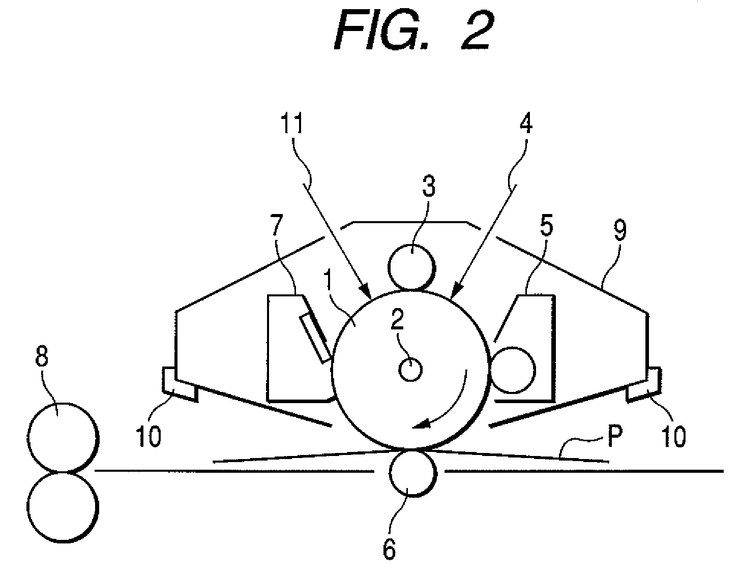
[0368]The electrophotographic photosensitive members and charging rollers produced as described above were each set in a modified machine of a laser beam printer LBP-2510, manufactured by CANON INC., and paper feed running (extensive operation) tests were conducted in an environment of 15° C. / 10% RH and an environment of 30° C. / 80% RH. Evaluation was made on images which were reproduced at the initial stage and after 5,000 sheets of paper were run. Details are as follows:

[0369]LBP-2510 was so modified as to be operated at a process speed of 190 mm / s. Evaluation was made using this modified machine, in which each electrophotographic photosensitive member and each charging roller were set in a cyan color process cartridge of LBP-2510 and this process cartridge was set in a cyan process cartridge station.

[0370]During the paper feed running, full-color printing was carried out in an intermittent mode in which a character image with a print percentage of 2% wa...


PUM


Abstract

In an electrophotographic photosensitive member having a support, a conductive layer formed on the support, an intermediate layer formed on the conductive layer, and a photosensitive layer formed on the intermediate layer, the conductive layer has been formed by using a conductive layer coating fluid which contains TiO2 particles coated with oxygen deficient SnO2 having an average particle diameter of from 0.20 μm or more to 0.60 μm or less, and has a volume resistivity of from more than 8.0×10⁸ Ωcm to 1.0×10¹¹ Ωcm or less. The electrophotographic photosensitive member can keep charging lines from occurring.

Description

TECHNICAL FIELD[0001]This invention relates to an electrophotographic photosensitive member, a process cartridge and an electrophotographic apparatus which have the electrophotographic photosensitive member, and also to a process for producing the electrophotographic photosensitive member.TECHNICAL BACKGROUND[0002]In recent years, research and development are energetically made on electrophotographic photosensitive members making use of organic photoconductive materials (i.e., organic electrophotographic photosensitive members).[0003]The electrophotographic photosensitive members are each basically constituted of a support and a photosensitive layer formed on the support. Under existing circumstances, however, various layers are often formed between the support and the photosensitive layer in order to, e.g., cover defects on the support surface, improve coating performance for the photosensitive layer, improve the adhesiveness between the support and the photosensitive layer, protec...

Claims


Application Information

Patent Timeline
Patent Type & Authority Patents(United States)
IPC IPC(8): G03G5/14
CPCG03G5/104G03G15/751G03G5/144
Inventor NAKAMURA, KAZUSHIGEHIRANO, HIDETOSHIUESUGI, HIROTOSHIKUMOI, HIROFUMITAKAGI, SHINJIABE, YUKIHIROKUNO, JUNPEIMIURA, DAISUKE
Owner CANON KK
Why Eureka
Try Eureka