Fuel cell

a fuel cell and cell technology, applied in the field of fuel cells, can solve the problems water condensation, performance degradation phenomenon, etc., and achieve the effect of preventing the supply of reaction gas, and reducing the power generation voltag

Active Publication Date: 2013-05-07
PANASONIC CORP
View PDF9 Cites 2 Cited by
  • Summary
  • Abstract
  • Description
  • Claims
  • Application Information

AI Technical Summary

Benefits of technology

[0018]In accordance with the present invention, it is possible to provide a fuel cell including a reaction gas supply path which makes it difficult to cause water condensation in a region near an end plate.

Problems solved by technology

Therefore, performance degradation phenomenon called “flooding” occurs, in which if the temperature of the pipe in a path is lower than the temperature of the reaction gas, water condensation occurs, impeding supply of the reaction gas and reducing a power generation voltage.
However, the heat insulating material cannot be wound around a portion inside the fuel cell 51, and consequently, water condensation may occur depending on the use condition.

Method used


Image

  • Fuel cell
  • Fuel cell
  • Fuel cell

Examples


embodiment 1

[0048

[0049]Embodiment 1 of the present invention will be described with reference to FIGS. 1 to 4.

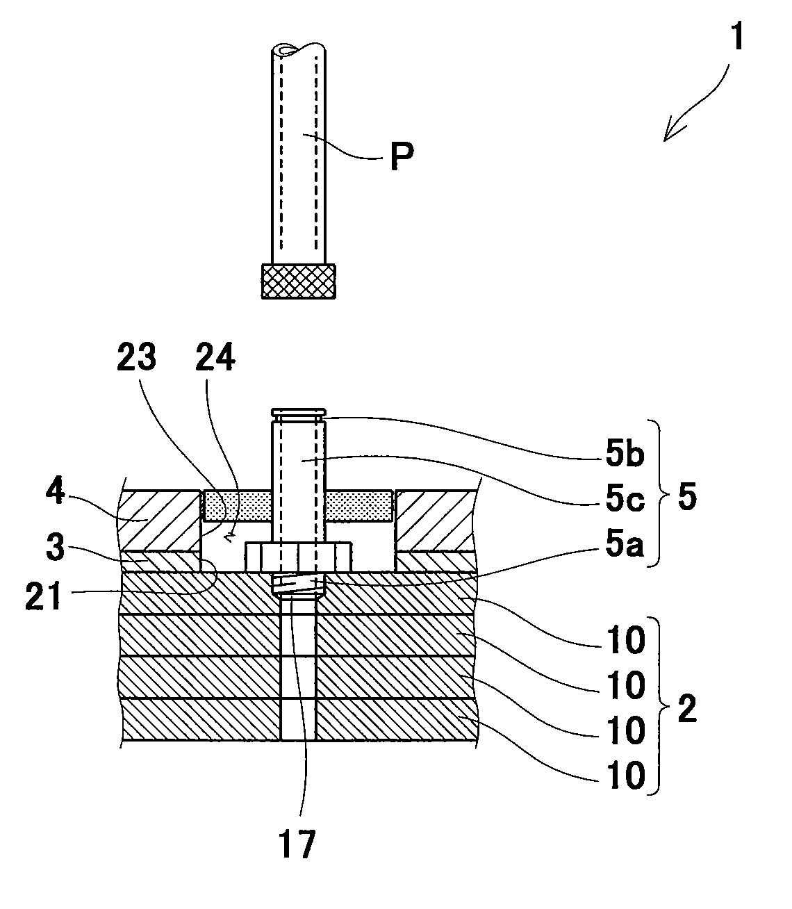
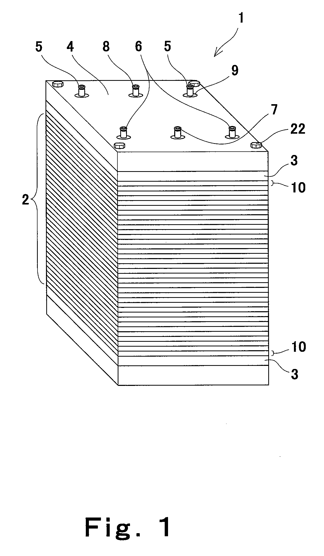
[0050]First of all, a fuel cell 1 according to Embodiment 1 will be described with reference to FIGS. 1 to 3. FIG. 1 is a perspective view of a fuel cell 1 according to Embodiment 1. As shown in FIG. 1, the fuel cell 1 of Embodiment 1 comprises a cell stack 2, current collectors 3, end plates 4, joints 5 to 8, and closing members 9.

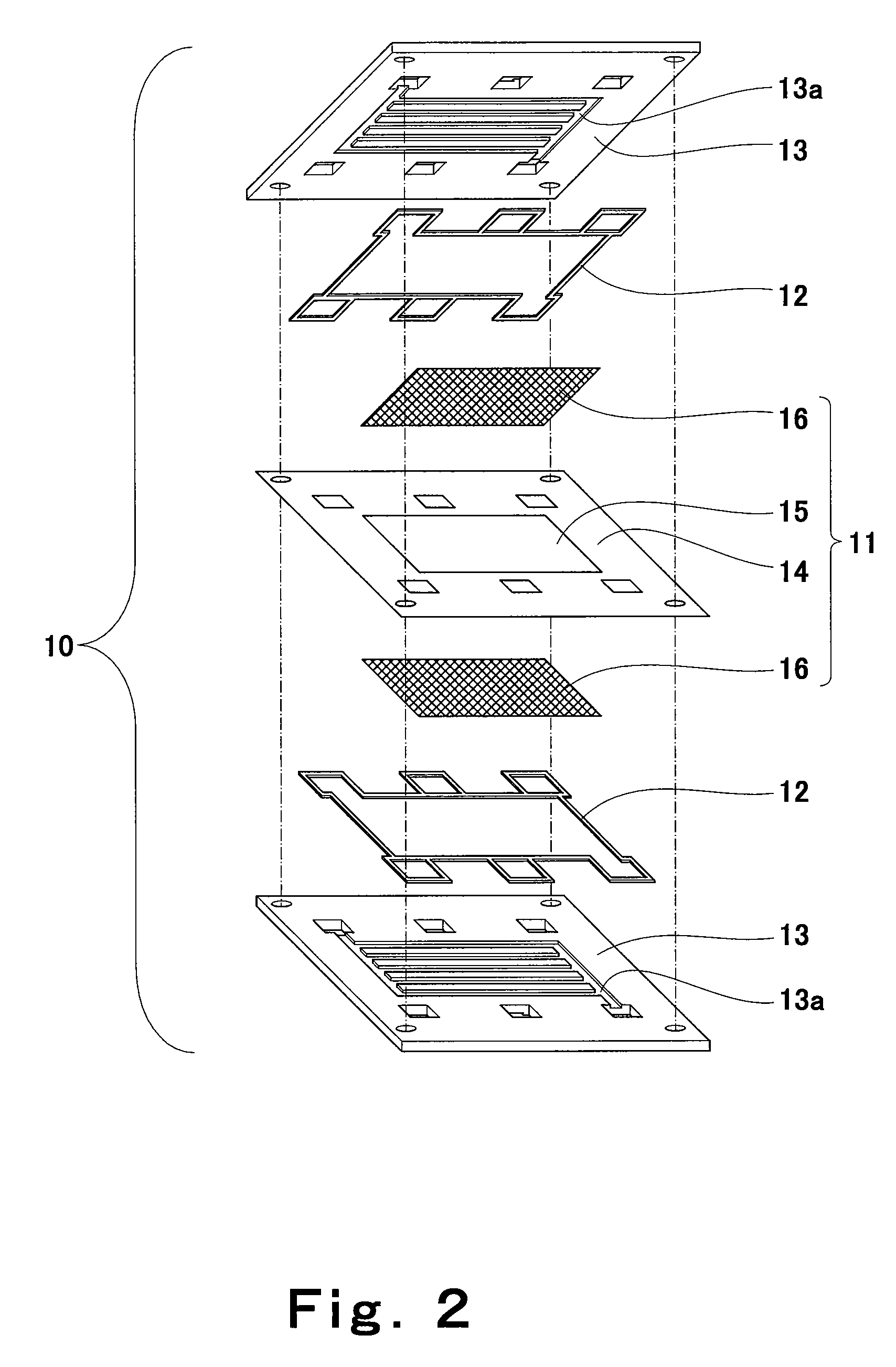
[0051]The cell stack 2 is formed to include plural cells 10 which are stacked. Typically, about 2 to 200 cells 10 are stacked to form the cell stack 2, according to a desired output electric power. FIG. 2 is an exploded perspective view of the cell 10 according to Embodiment 1. Each cell includes a MEA (Membrane Electrode Assembly) 11, gas seals 12 and separators 13.

[0052]The MEA 11 has a structure in which catalyst layers 15 are provided on both sides of a polymer electrolyte membrane 14 and gas diffusion layers 16 are stacked outside the catalyst layers 15....

embodiment 2

[0067

[0068]Subsequently, a fuel cell 1A according to Embodiment 2 will be described with reference to FIG. 5. The fuel cell 1A according to Embodiment 2 has the same structure as that of the fuel cell 1 of Embodiment 1 except for the joint and its surrounding portion, and therefore the structure of the fuel cell 1A except for the joint and its surrounding portion will not be described. For the same reason, in Embodiments 3 to 5 described later, the structure of the fuel cell except for the joint and its surrounding portion will not be described. FIG. 5 is an enlarged view of the joint 5 connected to the reaction gas supply inlet 17 and its surrounding portion in the fuel cell 1A according to Embodiment 2, in which FIG. 5(a) is a cross-sectional view and FIG. 5(b) is a perspective view. Herein, the structure of the joint 5 connected to the reaction gas supply inlet 17 and its surrounding portion will be described. The same occurs in the joints 6 to 8 and their surrounding portions. F...

embodiment 3

[0070

[0071]Subsequently, a fuel cell according to Embodiment 3 will be described with reference to FIG. 6. FIG. 6 is an enlarged view of the joint 5 connected to the reaction gas supply inlet 17 and its surrounding portion in the fuel cell 1B according to Embodiment 2, in which FIG. 6(a) is a cross-sectional view and FIG. 6(b) is a perspective view. Herein, the structure of the joint 5 connected to the reaction gas supply inlet 17 and its surrounding portion will be described. The same occurs in the joints 6 to 8 and their surrounding portions. As shown in FIG. 6, the fuel cell 1B according to Embodiment 3 has substantially the same structure as that of the fuel cell 1A according to Embodiment 2 but is different in structure from the fuel cell 1A according to Embodiment 2 in that the fuel cell 1A according to Embodiment 2 includes the closing member 9, while the fuel cell 1B according to Embodiment 3 does not include the closing member 9 but instead the through-hole 23 of the end pl...


PUM

PropertyMeasurementUnit
temperatureaaaaaaaaaa
diameteraaaaaaaaaa
inner diameteraaaaaaaaaa

Abstract

An object of the present invention is to provide a fuel cell including a reaction gas supply path which makes it difficult to cause water condensation in a region near an end plate. A fuel cell of the present invention comprises a cell stack 2 having a reaction gas passage 13a inside thereof and having on one end surface thereof a reaction gas supply inlet 17 from which a reaction gas is supplied to the reaction gas passage 13a, a joint 5 connecting the reaction gas supply inlet 17 to an external pipe P for supplying the reaction gas, plate-shaped end members 3, 4 which are disposed on one end surface of the cell stack 2 and have through-holes 21, 23 into which the joint 5 is inserted so as not to contact inner wall surfaces thereof, and a closing member 9 for substantially closing a space formed between the joint 5 and the inner wall surfaces of the through-holes 21, 23.

Description

RELATED APPLICATIONS[0001]This application is the U.S. National Phase under 35 U.S.C. §371 of International Application No. PCT / JP2008 / 004019, filed on Dec. 26, 2008, which in turn claims the benefit of Japanese Application No. 2007-340301, filed on Dec. 28, 2007, the disclosures of which Applications are incorporated by reference herein.TECHNICAL FIELD[0002]The present invention relates to a fuel cell. More particularly, the present invention relates to a fuel cell having a mechanism for preventing flooding.BACKGROUND ART[0003]Fuel cells generate electric power and heat simultaneously through an electrical chemical reaction between a fuel gas containing hydrogen and an oxidizing gas containing oxygen, such as air. The fuel cells are classified into various kinds according to a fuel or material used. One example is a polymer electrolyte fuel cell using a polymer electrolyte membrane. FIG. 11 is an enlarged view of an end portion of a conventional polymer electrolyte fuel cell 51. Th...

Claims


Application Information

Patent Timeline
Patent Type & Authority Patents(United States)
IPC IPC(8): H01M2/00H01M8/24
CPCH01M8/0247H01M8/04007H01M8/04089H01M8/241H01M8/04156Y02E60/50H01M8/242H01M8/2483
Inventor SHIBATA, SOICHIHATANO, SUSUMUKUSAKABE, HIROKIYASUMOTO, EIICHIMATSUMOTO, TOSHIHIRO
Owner PANASONIC CORP
Why Eureka
Try Eureka