Method of forming through hole in insulating substrate and method of manufacturing insulating substrate for interposer

a technology of insulating substrate and through hole, which is applied in the direction of manufacturing tools, metal working devices, welding/soldering/cutting articles, etc., can solve the problem of cracks in the insulating substra

Inactive Publication Date: 2014-08-07
ASAHI GLASS CO LTD
View PDF6 Cites 2 Cited by
  • Summary
  • Abstract
  • Description
  • Claims
  • Application Information

AI Technical Summary

Problems solved by technology

However, a crack may occur in the insulating substrate by accumulated thermal stress when a first through hol

Method used


Image

  • Method of forming through hole in insulating substrate and method of manufacturing insulating substrate for interposer
  • Method of forming through hole in insulating substrate and method of manufacturing insulating substrate for interposer
  • Method of forming through hole in insulating substrate and method of manufacturing insulating substrate for interposer

Examples


Embodiment Construction

[0021]A detailed description will hereinafter be given of embodiments of the present invention with reference to the drawings.

(Laser-Induced Electrical Discharge Machining Technique)

[0022]At first, a laser-induced electrical discharge machining technique used in an embodiment of the present invention is briefly described.

[0023]In the embodiment of the present invention, the “laser-induced electrical discharge machining technique” is an all-inclusive term of techniques of forming a through hole in an object to be processed by combining irradiation of laser beam onto the object to be processed with a discharge phenomenon between electrodes.

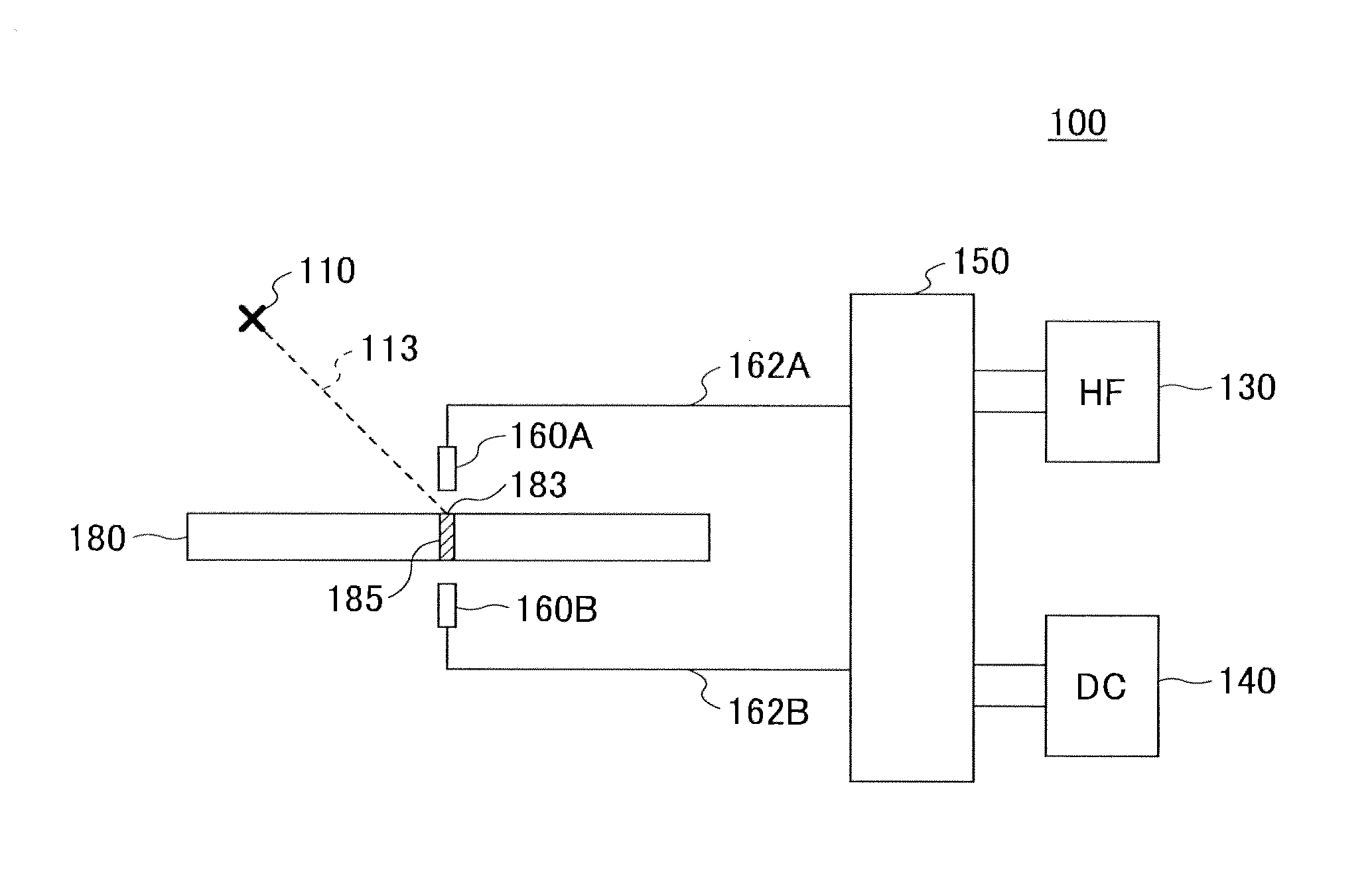
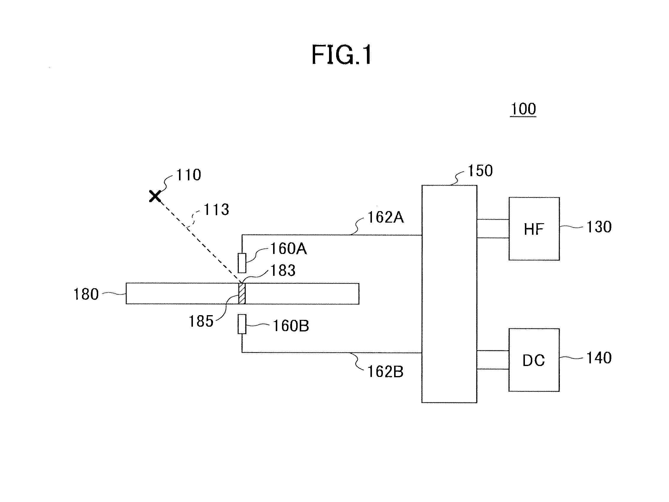
[0024]FIG. 1 schematically illustrates an exemplary structure of a laser-induced electrical discharge machine used for a laser-induced electrical discharge machining technique.

[0025]As illustrated in FIG. 1, the laser-induced electrical discharge machine 100 includes a laser beam source 110, a high-frequency high-voltage power source (HF) 130, a dir...


PUM

PropertyMeasurementUnit
Thicknessaaaaaaaaaa
Thicknessaaaaaaaaaa
Diameteraaaaaaaaaa

Abstract

A method including (a) preparing an insulating substrate, and (b) forming n (n is an integer equal to or greater than 9) through holes on the insulating substrate in a through hole density in a range of 1000 pieces/cm2 to 20000 pieces/cm2 at a pitch P (μm) in a range of 20 μm to 300 μm, wherein (b) is performed on a front surface of the insulating substrate and includes (b1) forming a first through hole at a first target position, (b2) forming a second through hole at a second target position, wherein a distance between the first target position and the second target position is greater than the pitch P (μm) . . . , and (bn) forming an n-th final through hole at an n-th target position, wherein a distance between the (n−1) target position and the n-th target position is greater than the pitch P (μm).

Description

CROSS-REFERENCE TO RELATED APPLICATIONS[0001]This application is a continuation application filed under 35 U.S.C. 111(a) claiming the benefit under 35 U.S.C. 120 and 365(c) of a PCT International Application No. PCT / JP2012 / 076360 filed on Oct. 11, 2012, which is based upon and claims the benefit of priority of the prior Japanese Patent Application No. 2011-231101 filed on Oct. 20, 2011, the entire contents of which are incorporated herein by reference.BACKGROUND OF THE INVENTION[0002]1. Field of the Invention[0003]The present invention relates to a method of forming a through hole in an insulating layer used at a time of manufacturing an interposer or the like.[0004]2. Description of the Related Art[0005]A fluorescent lamp may be put to various use, including an illumination for home use, a back light of a display unit, light irradiation at various stages of production, and the like.[0006]Conventionally, disclosed is a method of manufacturing an insulating substrate for an interpose...

Claims


Application Information

Patent Timeline
IPC IPC(8): B44C1/22
CPCB44C1/228B26F1/28H01L21/486H05K3/0029H05K2201/10378B26D7/1845H05K3/0017H05K2203/107B23K26/382B23K26/40B23K2103/50
Inventor TAKAHASHI, SHINTAROMORI, SATOSHI
Owner ASAHI GLASS CO LTD
Why Eureka
Try Eureka