Broadband reciprocal active balun structure

a balun structure and broadband technology, applied in the field of broadband mixers, can solve the problems of inability to use planar technology to produce circuits of this type for hyperfrequency operation, inability to operate over a very wide frequency band (more than two to three octaves), and inability to produce active structures in this way. reciprocal,

Inactive Publication Date: 2010-06-15
THALES SA
View PDF13 Cites 4 Cited by
  • Summary
  • Abstract
  • Description
  • Claims
  • Application Information

AI Technical Summary

Benefits of technology

[0019]The device according to the invention has the advantage of being a reciprocal active element which can provide one or other of the functions of a splitter balun or combiner balun on command.

Problems solved by technology

However, it is very difficult to use planar technology to produce a circuit of this type for operation at hyperfrequency.
Moreover, it cannot be used for operation over a very wide frequency band (more than two to three octaves) or at low frequency (f<1 GHz).
However, the active structures produced in this way are not reciprocal.
Unfortunately, therefore, it is necessary to produce two different structures in order to produce a splitter and a combiner.
If this type of structure is used in a mixer, the mixer will be unilateral.
Thus, regardless of which method is chosen, it is not possible at present to design an active balun, operating over a very wide frequency band (of the order of a decade), which is reciprocal and which can handle low frequencies (f≦1 GHz).
However, the use of passive couplers gives rise to problems of large overall dimensions, especially when operation at relatively low frequencies (around 1 GHz) is desired, since the passive coupler must always have a length of λ / 2 with respect to the central operating frequency of the mixing device in which it is incorporated.
This type of structure is therefore difficult to incorporate in MMIC technologies.
Moreover, because of its structure, a balun of this type cannot be used for broadband applications (covering several octaves).

Method used


Image

  • Broadband reciprocal active balun structure
  • Broadband reciprocal active balun structure
  • Broadband reciprocal active balun structure

Examples


Embodiment Construction

[0029]Let us start by considering FIGS. 3 and 4 which are schematic illustrations of the two active distributed structures from which the device according to the invention was developed.

[0030]These two basic structures are very fully described in the French patent application filed by the present applicant on 21 Dec. 2005 and published under the number 2 895 168. Consequently, their operation is not described in detail here, but the important elements will be indicated. FIG. 3 shows a first structure arranged to form a non-reciprocal active balun acting as a splitter device, while FIG. 4 shows a second structure arranged to form a non-reciprocal active balun acting as a combiner device.

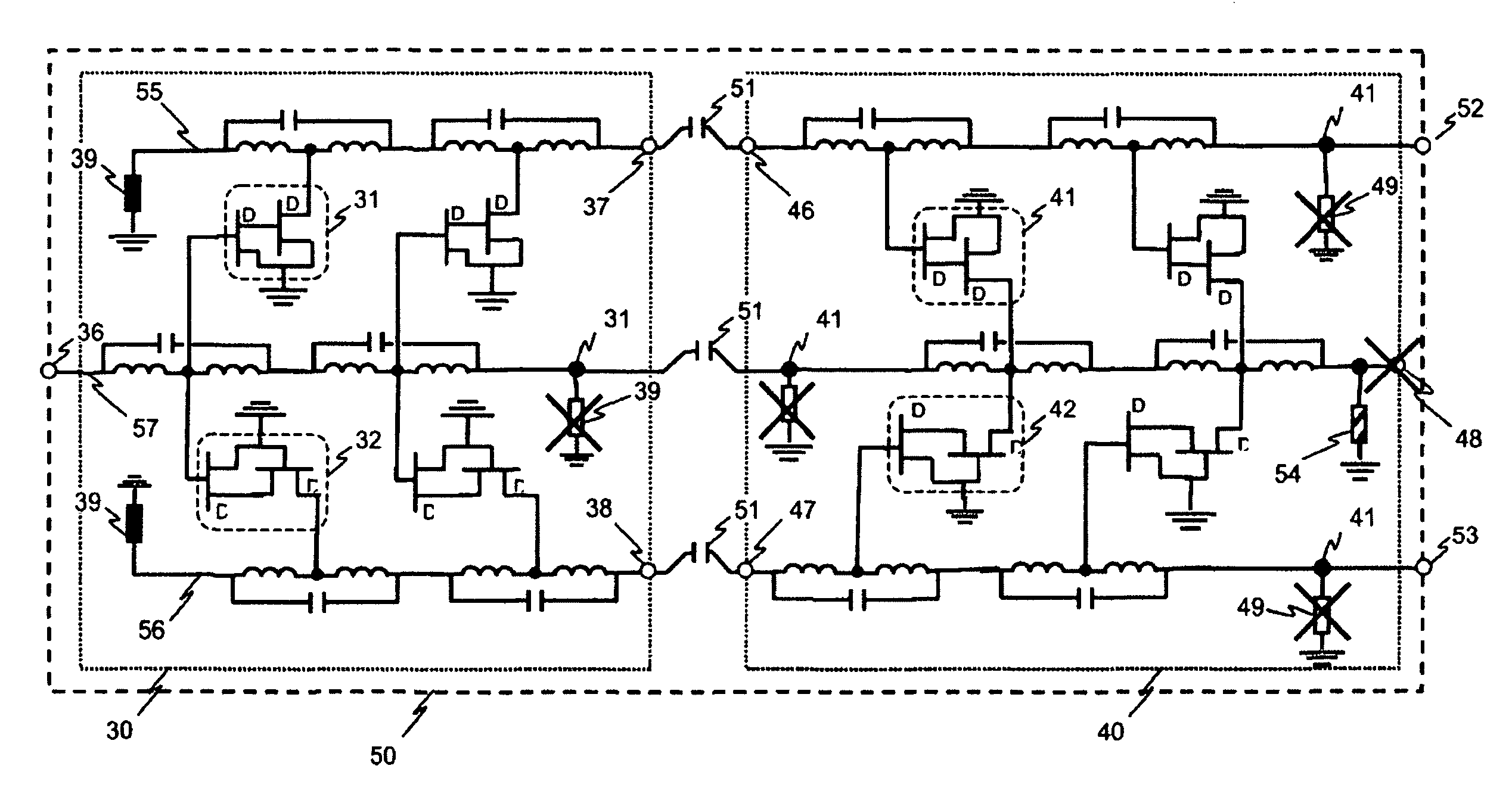
[0031]For this purpose, the structure of FIG. 3 has three transmission lines 33, 34 and 35, coupled by means of active amplifier cells 31 and 32, shown schematically in the drawing, each amplifier cell being formed from transistors (such as field-effect transistors) assembled to form a circuit of the ...


PUM


Abstract

The present invention relates to the field of electronic devices known as baluns. It concerns an active balun which is broadband and reciprocal. Embodiments of the invention integrate an active splitter balun with an active combiner balun so as to form three transmission lines. A first active coupling is provided between the first and second transmission lines and a second active coupling is provided between the first and third transmission lines. The active couplings are provided by means of amplifier cells distributed along the transmission lines. Embodiments of the invention have configurable means for polarizing the different amplifier cells so as to create a specific coupling direction between the various transmission lines. The device according to the invention can be applied in the field of broadband mixers which are used, notably, in radio transmission and reception circuits.

Description

[0001]The present application claims priority under 35 U.S.C. §119 of French patent application No. 0707855000, which was filed in the French Patent Office on Nov. 9, 2007 and which is incorporated by reference herein in its entirety.FIELD OF THE INVENTION[0002]The present invention relates to the field of electronic devices known as baluns, and more specifically to the field of broadband mixers, used notably in radio transmission and reception circuits, and produced with the use of baluns.BACKGROUND OF THE INVENTION[0003]There is a significant demand for broadband mixers in present-day industry. These circuits are used in some reception and transmission circuits. It is possible to envisage numerous architectures for the production of mixers. These include, in particular, what are known as “balanced” or “double-balanced” structures which offer the best performance in terms of parasitic frequency rejection and very good channel isolation. There is a known way of producing a double-ba...

Claims


Application Information

Patent Timeline
Patent Type & Authority Patents(United States)
IPC IPC(8): H03F3/04
CPCH03F1/223H03F3/604H03F3/607H03F3/62H03H11/32H03D7/1458H03F3/211H03D2200/0023H03F2200/06H03F2200/09H03F2200/451H03F2200/534H03F2200/537H03F2200/541H03F2200/543
Inventor PLAZE, JEAN-PHILIPPEDUEME, PHILIPPEMALLET-GUY, BENOIT
Owner THALES SA
Why Eureka
Try Eureka