
Suction device for a pick power tool

a technology of suction device and power tool, which is applied in the direction of percussive tools, manufacturing tools, transportation and packaging, etc., can solve the problem of limited aspiration size of removed material pieces, and achieve the effect of preventing the blockage of suction lines

Active Publication Date: 2010-06-22
HILTI AG
View PDF28 Cites 56 Cited by
  • Summary
  • Abstract
  • Description
  • Claims
  • Application Information

AI Technical Summary

Benefits of technology

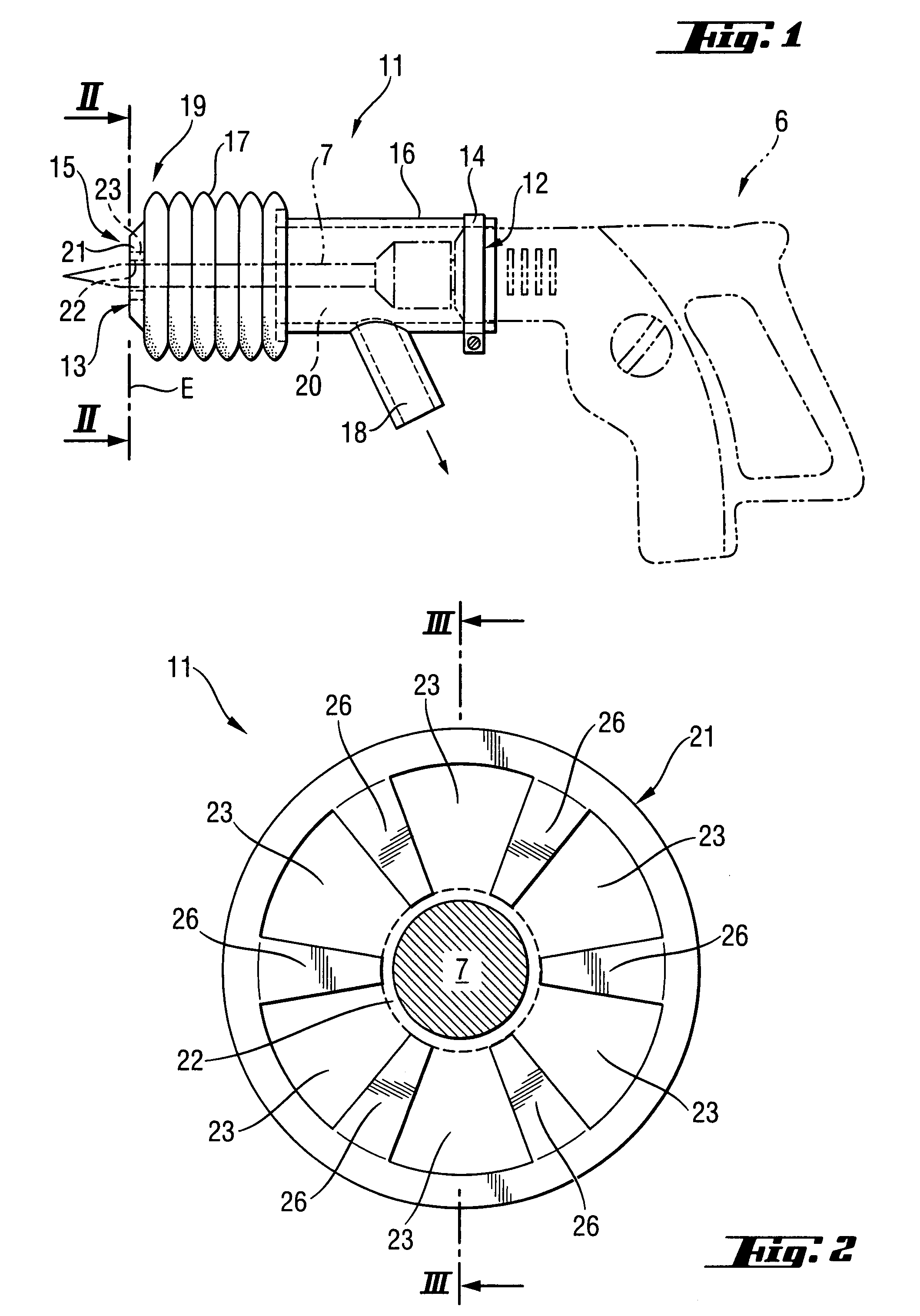
[0010]The through-opening for the working tool forms a guide for the suction device and prevents kinking in the latter in spite of the flexible portion of the suction device. Depending on the shape and number of the well-defined suction openings, the suction flow can be influenced and, therefore, controlled during aspiration as well as within the suction chamber of the suction device, which leads to an improved suction, particularly of the occurring dust particles, in the different working positions of the suction device. Due to the design of the at least one suction opening, the maximum size of the aspirated pieces of the removed material is limited, which prevents clogging of the suction channels. The retaining element forms a diaphragm which prevents large pieces of removed material from being aspirated into the suction device. The retaining element is advantageously made of a permanently elastic material.
[0021]The at least one suction opening preferably has a maximum cross-sectional extension of less than 30 mm so that larger pieces of removed material are not aspirated and, with a corresponding construction of the cross section of the suction lines, clogging the suction lines is prevented. When a suction line with a larger cross-section is provided and the used vacuum source has a sufficient suction power, the maximum cross-sectional extension of the at least one suction opening can also be larger.

Problems solved by technology

Due to the design of the at least one suction opening, the maximum size of the aspirated pieces of the removed material is limited, which prevents clogging of the suction channels.

Method used


Image

  • Suction device for a pick power tool
  • Suction device for a pick power tool
  • Suction device for a pick power tool

Examples


Embodiment Construction

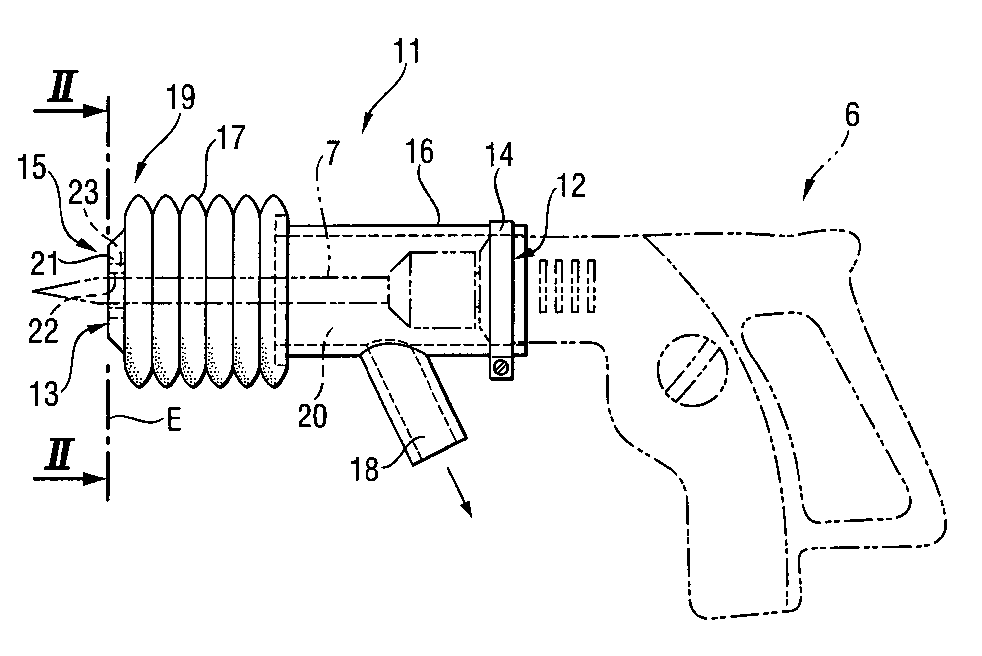
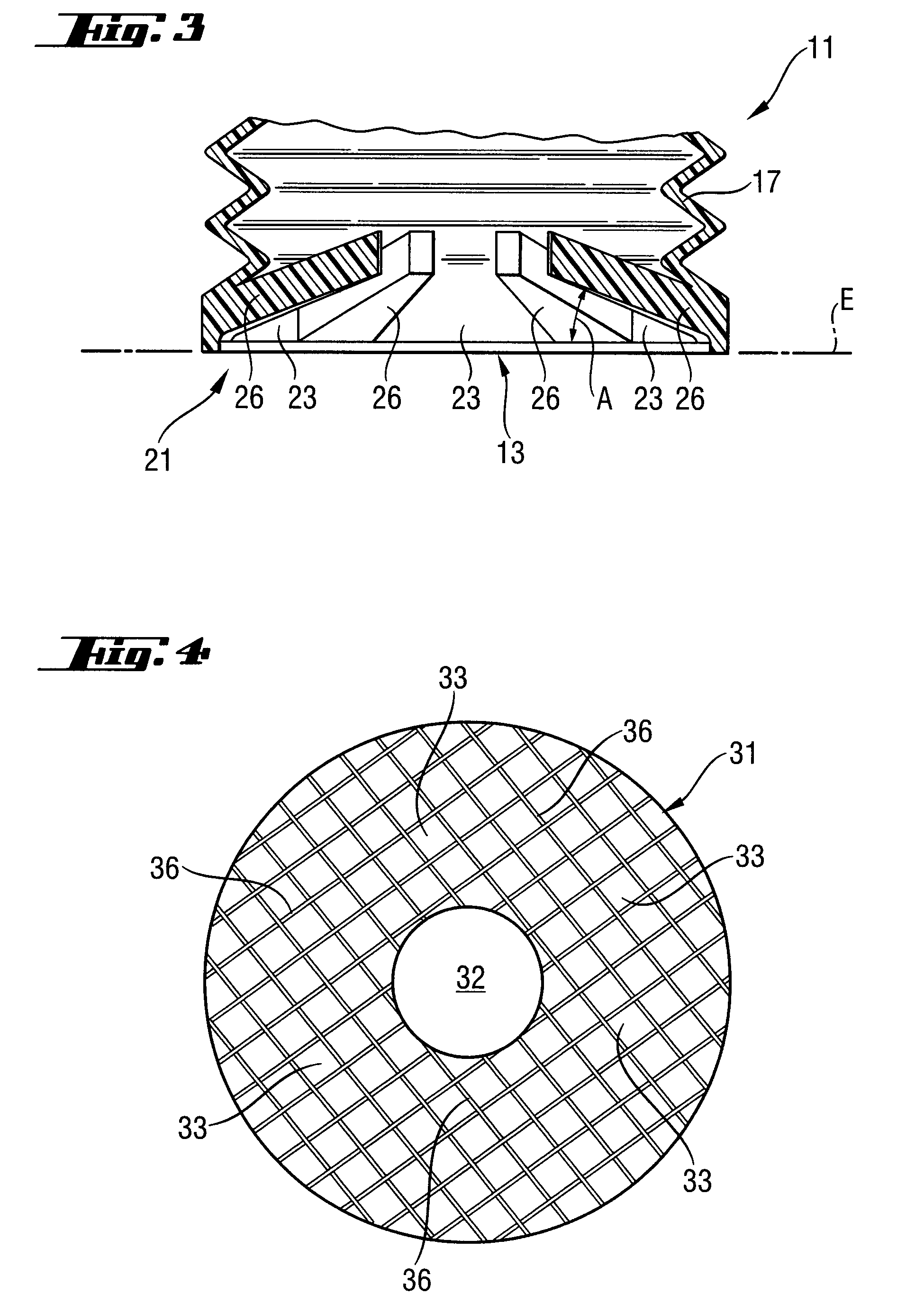
[0032]The suction device 11 shown in FIGS. 1 to 3 is arranged at a pick power tool 6 formed as a combi-hammer. A securing device 14 in the form of a collar band for detachably securing the suction device 11 to the pick power tool 6 is provided at a first end 12 of the suction device 11. At its second end 13, the suction device 11 has a contact area 15 with which the suction device 11 contacts a constructional component. The suction device 11 has a rigid portion 16 which extends from the first end 12 in direction of the second end 13, and a flexible portion 17 which extends from the rigid portion 16 to the second end 13 of the suction device 11 and which can be reduced in a longitudinal direction parallel to the longitudinal extension of the working tool 7. The rigid portion 16 and the flexible portion 17 form a receiving space 20 which partially encloses a working tool 7 arranged in the pick power tool 6. A connection piece for a vacuum source, not shown, is provided at the rigid po...


PUM

PropertyMeasurementUnit
areaaaaaaaaaaa
suctionaaaaaaaaaa
distanceaaaaaaaaaa

Abstract

A suction device (11) for a hammer drill (6) has a first end (12) with a securing device (14) for securing the suction device (11) to the hammer drill (6) and a second end (13) opposite first end (12) and which has a contact area (15) with which the suction device (11) contacts a constructional component, the suction device (11) further having a receiving space (20) which at least partially encloses a working tool (7) of the pick power tool (6), and being provided with a connection device (18) for a vacuum source. A retaining element (21) having a through-opening (22) for the working tool (7) and a plurality of suction openings (23) is provided in an area (19) of the second end (13).

Description

BACKGROUND OF THE INVENTION[0001]1. Field of the Invention[0002]The invention is directed to a suction device for a pick power tool including a suction device for a pick power tool, comprising a receiving space which at least partially encloses a working tool of the pick power tool, a securing device provided at a first end of the suction device for securing the suction device to the pick power tool, a contact area provided at a second end of the suction device opposite the first end for contacting a constructional component, a connection device for a vacuum source.[0003]2. Description of the Prior Art[0004]When a mineral constructional component such as, for example, a concrete wall or concrete floor is worked by a working tool of a pick power tool such as a drill hammer, combi-hammer or chisel hammer, pieces of the broken material and dust occur. The dust particles, in particular, lead to a contamination of the environment, e.g., of interior spaces of a building, and impede the wo...

Claims


Application Information

Patent Timeline
Patent Type & Authority Patents(United States)
IPC IPC(8): B23B27/10
CPCB25D17/20B23Q11/0046B23B2270/30Y10T408/453
Inventor BLEICHER, JOCHENOHLENDORF, OLIVER
Owner HILTI AG
Learn More