Drawer buffer and drawer slide rail with drawer buffer

a technology of slide rails and buffers, which is applied in the direction of drawers, furniture parts, household applications, etc., can solve the problems of affecting the feeling of users and people around, the applicability of products is not satisfying in practical use, and the drawer tends to make loud noises, etc., to achieve the effect of increasing the air capacity of the cylinder, expanding the stroke of the piston rod, and increasing the buffering power

Inactive Publication Date: 2010-06-22
HSIEH YIN WANG +1
View PDF6 Cites 8 Cited by
  • Summary
  • Abstract
  • Description
  • Claims
  • Application Information

AI Technical Summary

Benefits of technology

[0008]The benefits of this invention are: because the section of the cylinder sleeve and piston rod is similar to the ellipse, the air capacity of the cylinder can be raised, the buffering power increased and the stroke of piston rod expanded; in addition, the piston rod of this invention has more than two parts that greatly increases the buffering stroke (at least 60 mm), and thus makes the drawer harder to slide out by vibration and harder to make loud noises to affect the feeling of the user the people around it.

Problems solved by technology

The drawer is a common component of furniture, it is installed in the drawer cavity by the slide rail on furniture; ordinary drawers are easy to slide out because of the vibration, and the goods in them will be dropped out; in addition, the drawer tends to make loud noises when being closed, and affects the feeling of the user and people around it.
At present, the section shape of cylinder sleeve and piston rod of buffers used for drawer buffers and drawer slide rails with drawer buffer in the market are all round; the air capacity of the cylinder sleeve is small, the buffering power is insufficient and the stroke of the piston rod is limited; furthermore, the cylinder of them consists of only one part of cylinder sleeve and one part of piston rod, and the stroke of the piston rod is relatively small; the applicability of the product is not satisfying in practical use because the limited stroke of the piston (less than 60 mm).

Method used


Image

  • Drawer buffer and drawer slide rail with drawer buffer
  • Drawer buffer and drawer slide rail with drawer buffer
  • Drawer buffer and drawer slide rail with drawer buffer

Examples


Embodiment Construction

[0024]The following is just one good example of the implementation of this invention, it, therefore, does not limit the protection scope of this invention.

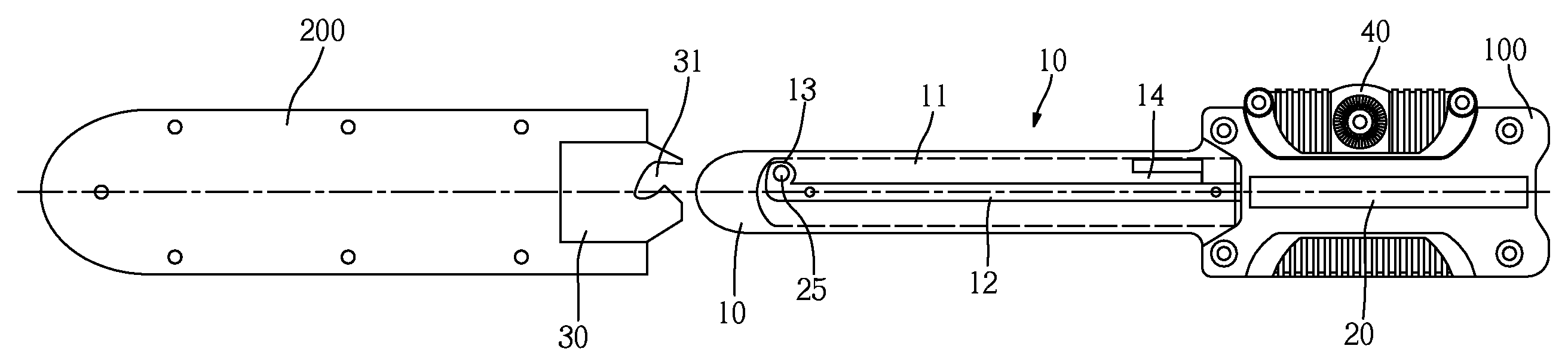
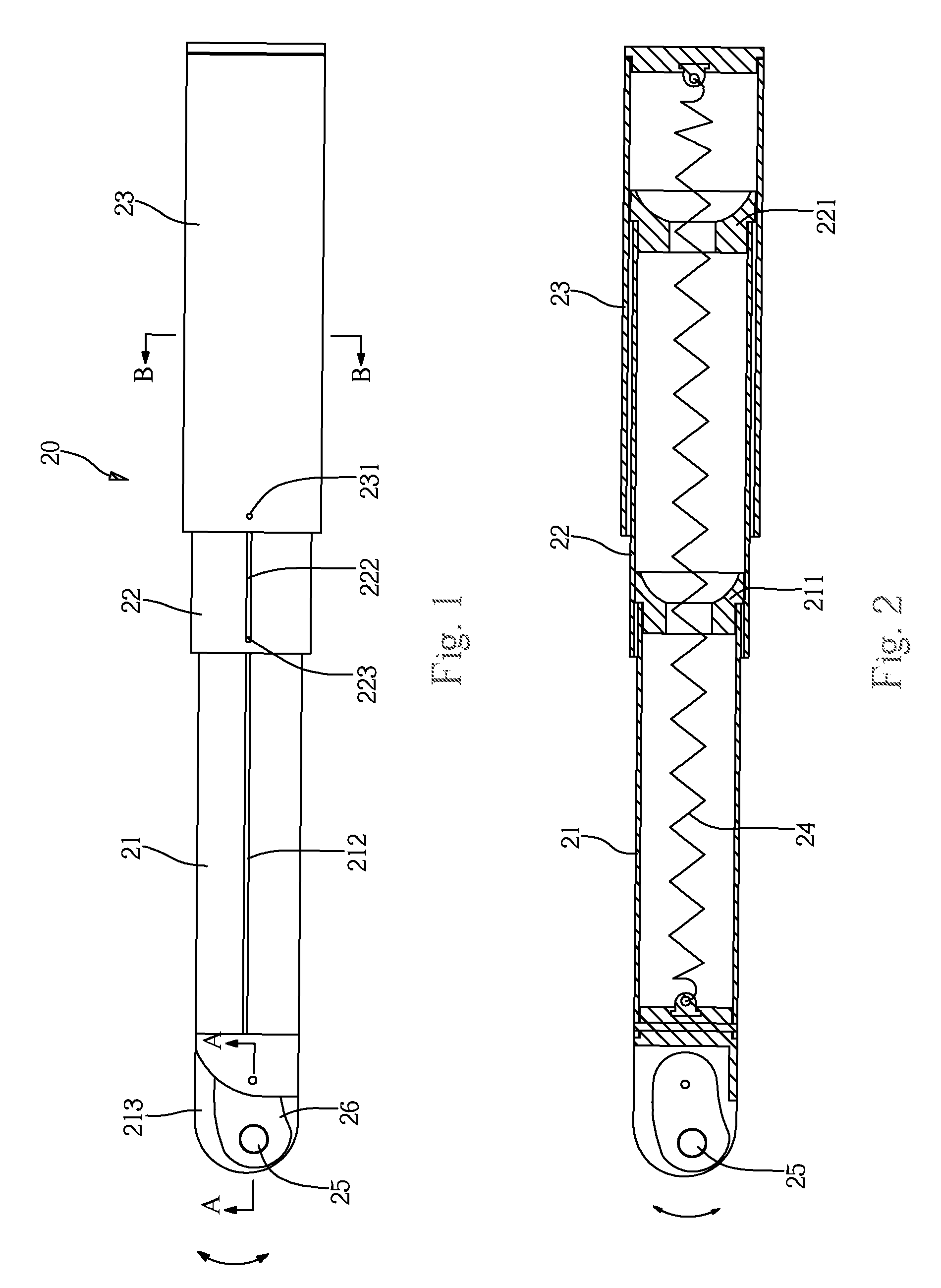
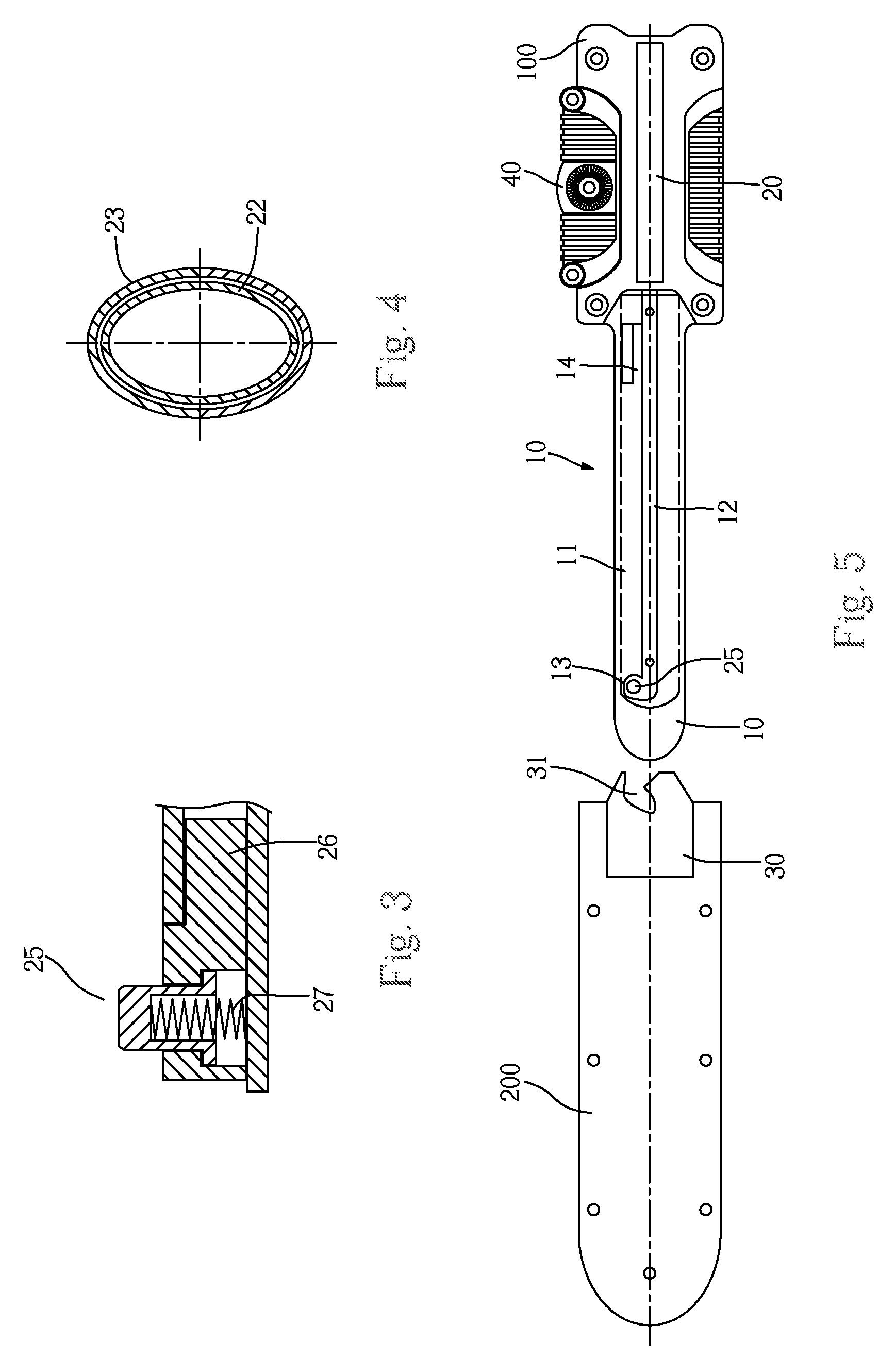
[0025]First of all, please refer to the Attached Diagrams 1 to 5: this invention of drawer buffer includes: base 100, cylinder 20 and plate 30 (plate 30 can be installed in the front end of a sliding sleeve 200 used for containing guide rod 10) with the guide rod 10 projected in the front end; cylinder 20 is fixed in base 100, one, two or more parts of the piston rod can be used in accordance with requirements. This example of implementation takes the condition that the piston has two parts to elaborate its principle; the diagram shows that there are piston rings 211 and 221 with holes in the middle in the tail of first part piston rod 21 and the second part piston rod 22 respectively; the material of piston rings 211 and 221 should be plastics to improve the sealing performance of the cylinder and increase the buffering power; pi...


PUM


Abstract

A drawer Buffer includes: the base, cylinder and plate with the guide rod projected in the front end; the cylinder of which is fixed in the base and there is a projecting column on the front end of its piston rod; in the middle of the guide rod, there is a sliding chute for the move of piston rod; in the outer side of the guide rod, there is a guideway to coordinate with the projecting column, the front end of the guideway is linked with a positioning slot; on the plate, there is the guiding slot for traction and pushing the projecting column into the positioning slot; the section shape of the mentioned cylinder sleeve and piston rod of the cylinder is similar to the ellipse, the tail of the cylinder sleeve is linked with the head of piston rod via the spring. The buffer can be used with a drawer slide rail for drawer moving reposefully.

Description

CROSS REFERENCE TO RELATED PATENT APPLICATION[0001]This application claims the priority of the Chinese patent application No. 200620155144.5, which has a filing date of Dec. 25, 2006.FIELD OF THE INVENTION[0002]This new invention relates a type of drawer buffer and a type of drawer slide rail with drawer buffer.BACKGROUND OF THE INVENTION[0003]The drawer is a common component of furniture, it is installed in the drawer cavity by the slide rail on furniture; ordinary drawers are easy to slide out because of the vibration, and the goods in them will be dropped out; in addition, the drawer tends to make loud noises when being closed, and affects the feeling of the user and people around it. To solve this problem, various types of drawer buffers were developed by the personnel in the industry; among others, there is one type of drawer buffer consisting of the base, cylinder and plate with projected guide rod on the front end; the cylinder is fixed in the base and the base is fixed on th...

Claims


Application Information

Patent Timeline
Patent Type & Authority Patents(United States)
IPC IPC(8): A47B88/04
CPCA47B88/04A47B2210/0018A47B88/473A47B88/40
Inventor HSIEH, YIN-WANG
Owner HSIEH YIN WANG
Why Eureka
Try Eureka