Gas-insulated equipment
a technology of gas-insulated equipment and high-voltage conductors, which is applied in the direction of air-break switches, non-enclosed substations, substations, etc., can solve the problems of insufficient dielectric strength of bare electrode high-voltage conductors, and the inability to achieve the improvement of the dielectric strength of the entire electrode system needed for miniaturization of the device, so as to achieve efficient improvement of the dielectric strength of the entire system and improve the effect of insulation coordination
- Summary
- Abstract
- Description
- Claims
- Application Information
AI Technical Summary
Benefits of technology
Problems solved by technology
Method used
Image
Examples
first embodiment
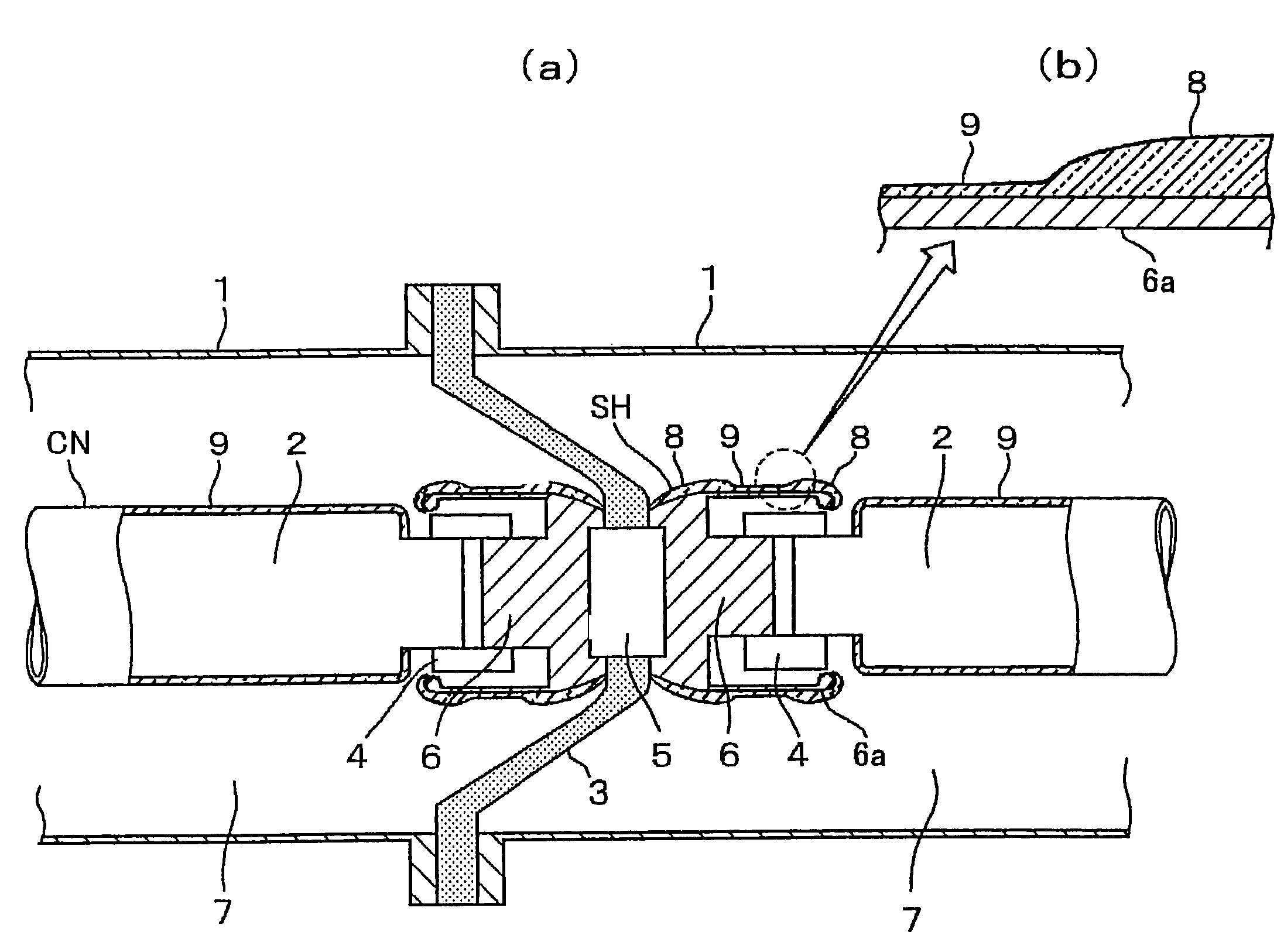
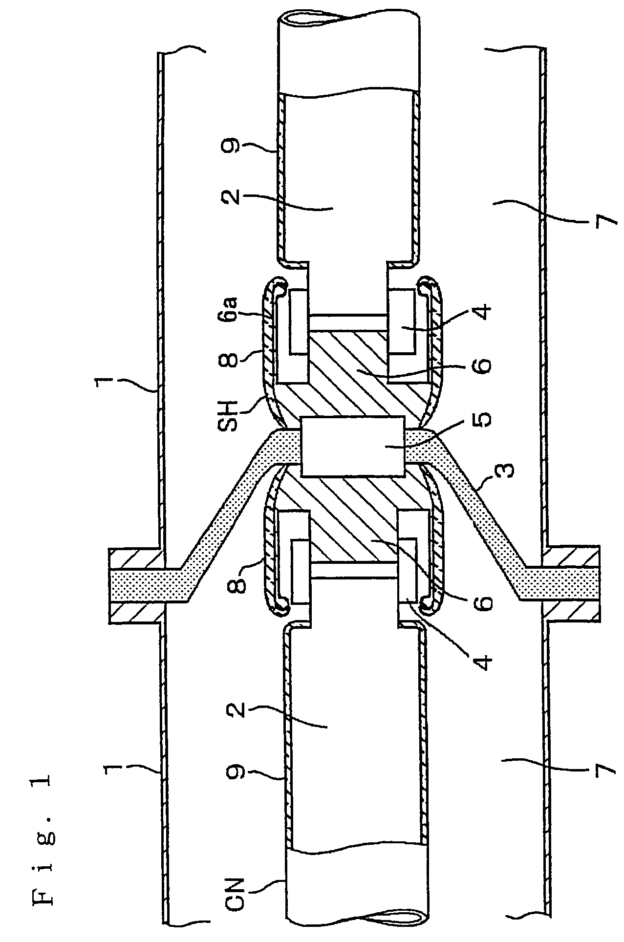
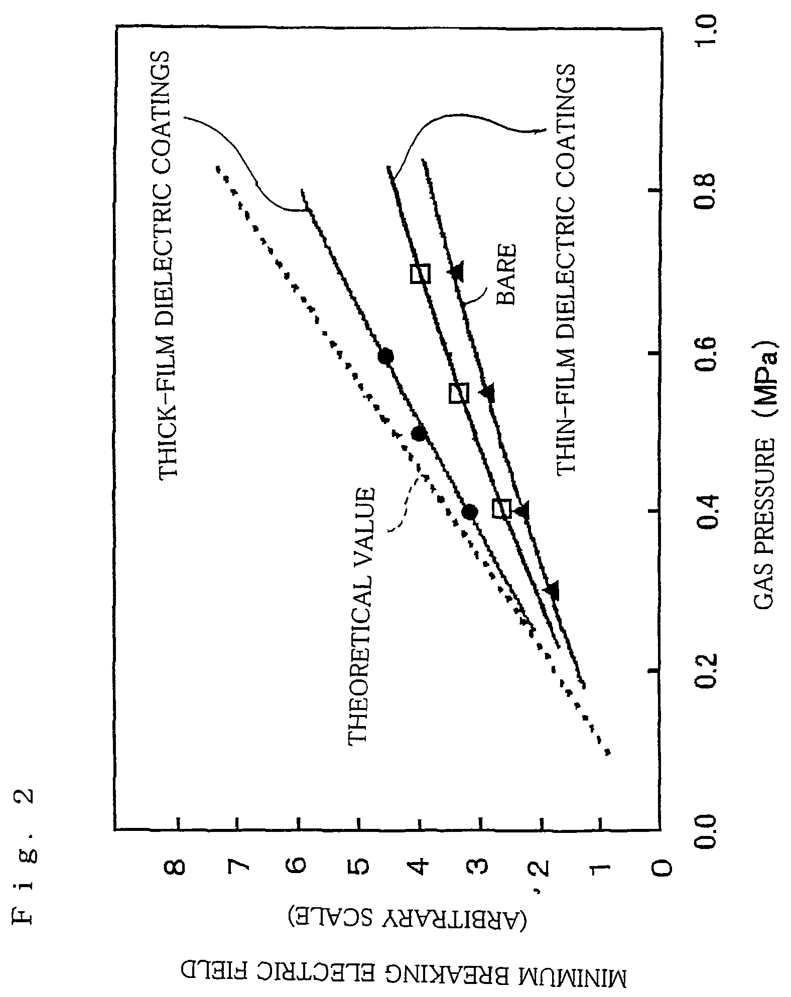
[0015]A first embodiment according to the invention is hereinafter described with reference to FIGS. 1 and 2. FIG. 1 is a cross-sectional view of a structure of a gas-insulated switchgear in the first embodiment according to the invention. FIG. 2 is a characteristic diagram showing relationships between gas pressure and the minimum breakdown electric fields generated at thick dielectric coating, thin dielectric coating, and bare electrode as basic data of the invention.
[0016]FIG. 1 illustrates the gas-insulated switchgear in the first embodiment according to the invention, particularly showing a connection between parts. In this example, an insulating spacer 3 is used to connect one and the other earth metal containers 1, and one and the other high-voltage conductors 2. Shielding electrodes 6 having a larger diameter than that of the high-voltage conductors 2 are also provided to reduce electric field at live contacts 4, which form an electric path at the connection, and an embedded...
second embodiment
[0026]A second embodiment according to the invention is now described with reference to FIGS. 3 through 6. FIG. 3 is a cross-sectional view showing a structure of a gas-insulated switchgear in the second embodiment according to the invention. FIG. 4 is a characteristic diagram showing the relationship between breakdown electric field at an electrode covered with dielectric coating and the thickness of the dielectric coating as basic data for the invention. FIG. 5 is a diagram showing dependency of breakdown electric field at an electrode on effective electrode area used as reference data for explaining advantages of the invention (quoted from the Electricity Society: Electric Discharge Handbook, Ohmsha, 1998). FIGS. 6A and 6B are cross-sectional views showing a structure example of a gas-insulated switchgear. In FIGS. 6A and 6B, 90% of a larger part of the area at which the maximum electric field is generated is covered with thick dielectric coating, and the rest of the area is cove...
PUM
 Abstract
Description
Claims
Application Information
 - R&D
- Intellectual Property
- Life Sciences
- Materials
- Tech Scout
- Unparalleled Data Quality
- Higher Quality Content
- 60% Fewer Hallucinations
Browse by: Latest US Patents, China's latest patents, Technical Efficacy Thesaurus, Application Domain, Technology Topic, Popular Technical Reports.
© 2025 PatSnap. All rights reserved.Legal|Privacy policy|Modern Slavery Act Transparency Statement|Sitemap|About US| Contact US: help@patsnap.com


