X-ray tube with an anode isolation element for liquid cooling and a receptacle for a high-voltage plug

a technology of anode isolation element and x-ray tube, which is applied in the direction of x-ray tubes, electric discharge tubes, x-ray apparatuses, etc., can solve the problems of large diameter of tubes, risk of instability, and short overall length of tubes, so as to facilitate the upkeep of pipe structures and facilitate maintenance. , the effect of reducing the risk of instability

Active Publication Date: 2010-05-06
COMET HOLDING
View PDF0 Cites 25 Cited by
  • Summary
  • Abstract
  • Description
  • Claims
  • Application Information

AI Technical Summary

Benefits of technology

[0016]In still another embodiment variant, the pipe structure is integrated into the surface of the high-voltage plug. The most important advantage of this embodiment variant lies above all in the very easy access to the pipe structure, akin to the embodiment variant with the pipe structure in the surface of the anode insulation element. That makes possible above all very easy control or respectively very easy upkeep of the pipe structure, whereby the maintenance is also considerably simplified. However, made possible by means of this embodiment variant is the use of standardized anode insulation elements (i.e. such as are also usable with unipolar X-ray tubes, for example), while the pipe structure comes to lie exclusively within the high-voltage plug.
[0017]In another embodiment variant, the pipe structure is integrated into an intermediate element, the intermediate element being disposed between the anode insulation element and the high-voltage plug. The advantage of this embodiment variant lies in particular in that both standardized high-voltage plugs and standardized anode insulation elements are usable. Thus the pipe structure for guiding of the coolant is integrated into a completely new element, which can be manufactured and also installed separately. Also the maintenance of such a pipe structure is thereby especially simplified. In the case of failure or massive damage to the pipe structure, the intermediate element can also be very easily replaced, without the entire anode insulation element and/or the high-voltage plug being used also being affected.
[0018]In still another embodiment variant, the at least one inflow channel and/or the at least one outflow channel are o

Problems solved by technology

The use of disc-shaped insulators thus leads to tubes with large diameter but short overall length.
The drawbacks of this solution consist in that the tube is given a large diameter and—owing to the lead covering necessary for reasons of radiation protection—a large amount of weight.
Furthermore, for reasons relating to high voltage technology, the ceramic disc element is not ideal since the direction of field strength runs parallel to the ceramic surface, and thus there exists the risk of instability through flashover.
Through the installation of a special adapter moreover two separate insulation bounding surfaces occur, which represent additi

Method used


Image

  • X-ray tube with an anode isolation element for liquid cooling and a receptacle for a high-voltage plug
  • X-ray tube with an anode isolation element for liquid cooling and a receptacle for a high-voltage plug
  • X-ray tube with an anode isolation element for liquid cooling and a receptacle for a high-voltage plug

Examples


Embodiment Construction

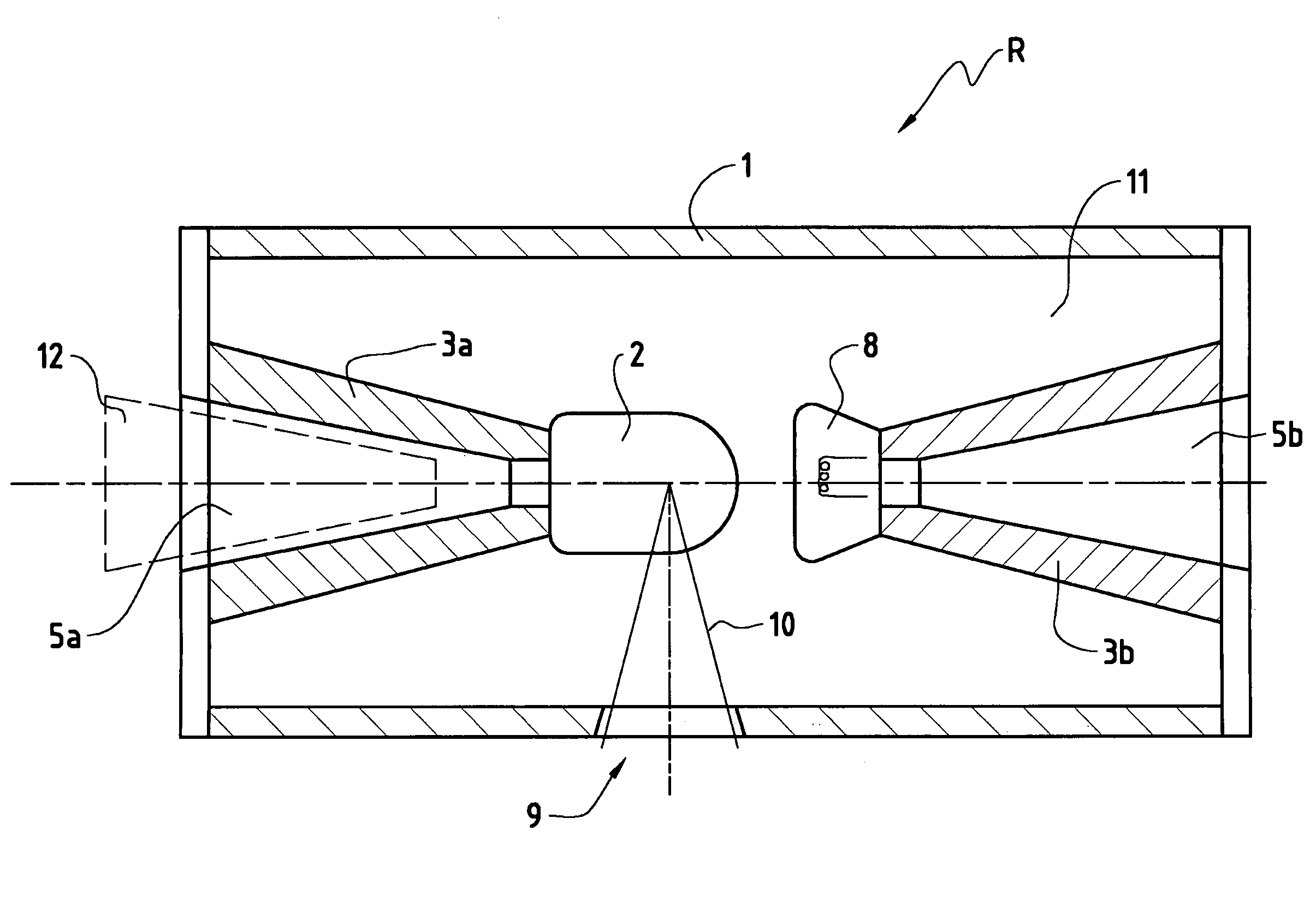
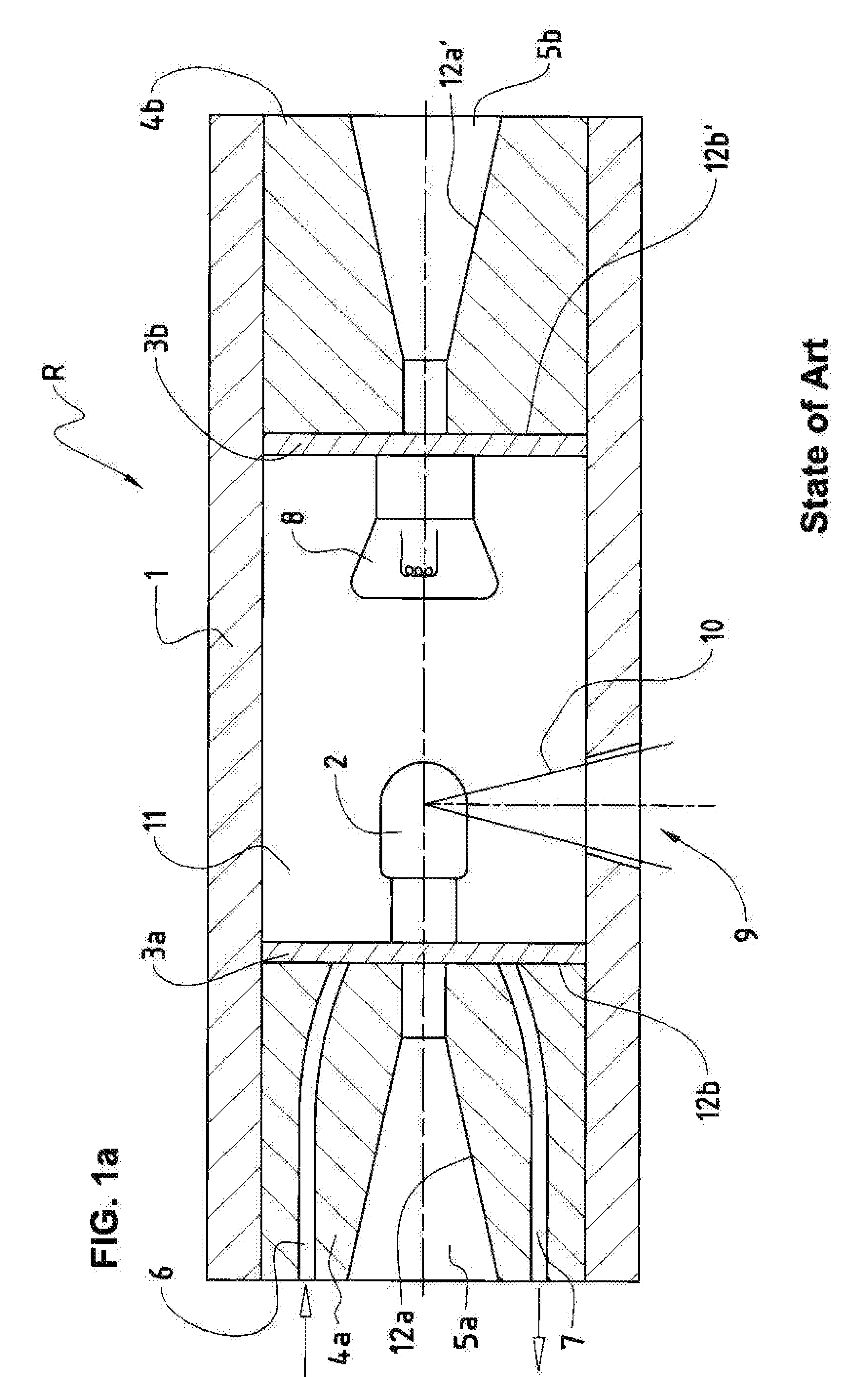
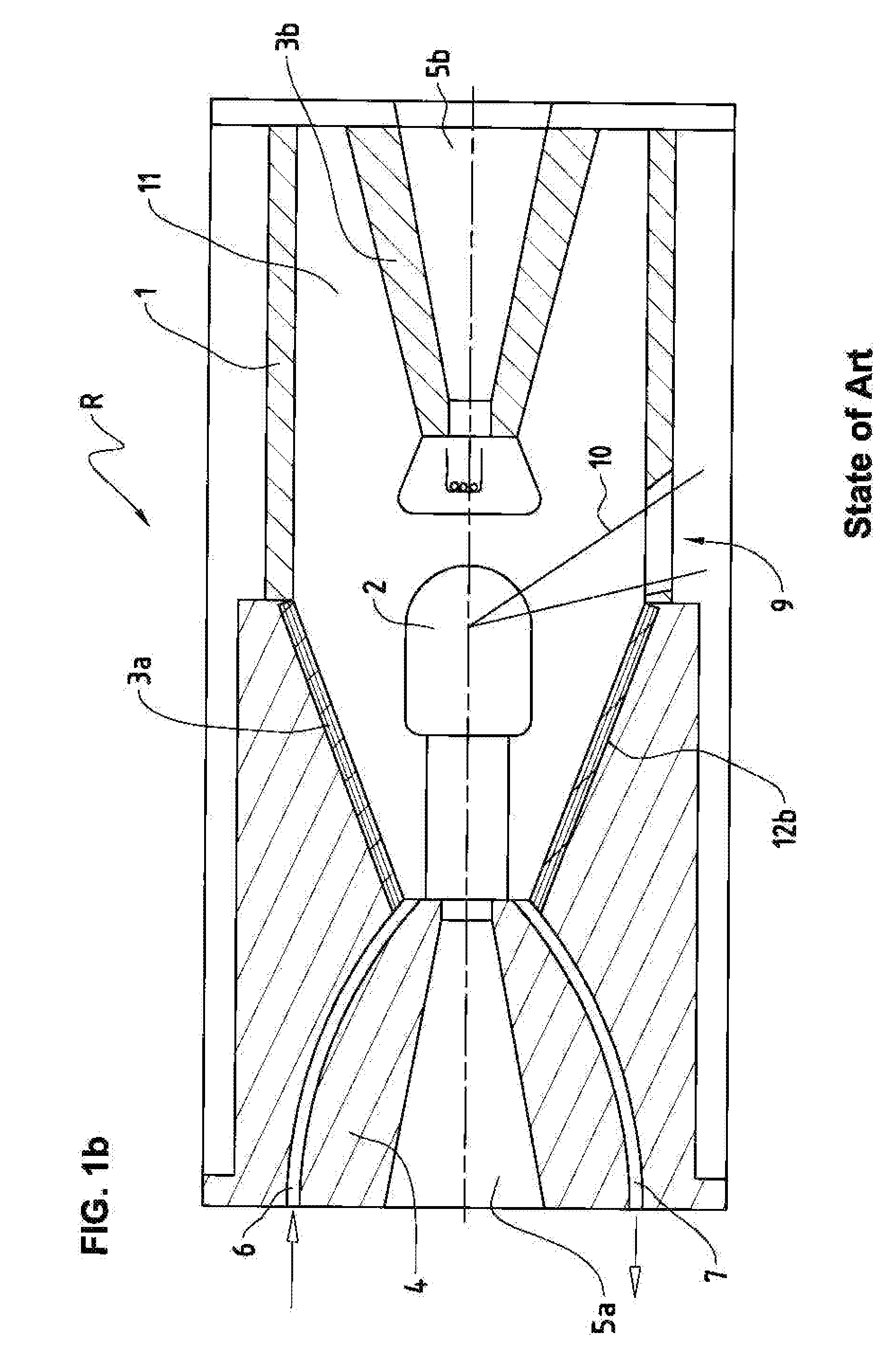
[0032]FIG. 1a shows diagrammatically a high-voltage X-ray tube R from the state of the art. The high-voltage X-ray tube R has, among other things, an outer jacket or lead covering 1, by means of which an inner space 11 is closed off and sealed off. Normally the high-voltage X-ray tube R is of coaxial design, as is shown by a central axis in FIG. 1a. The inner space 11 is essentially under vacuum, which vacuum is generated once during the manufacture of the high-voltage X-ray tube R. In this inner space 11, an anode 2 and a cathode 8 are situated opposite one another. By means of applied high voltage, electrons e- are accelerated from the cathode 8 to the anode 2. X-rays 10 are thereby created at the anode 2, which X-rays are emitted through an exit aperture 9 in the lead covering 1 into the surrounding area.

[0033]The anode 2 and the cathode 8 are insulated by disc-shaped insulation elements from the lead covering 1. The anode insulation element 3a and the cathode insulation element ...


PUM


Abstract

The present invention relates to a high-voltage x-ray tube (R) with an inner vacuum chamber (11) in which lie, oriented opposite one another, a cathode (8) held at a negative high voltage during operating conditions and an anode (2) held at a positive high voltage during operating conditions, wherein the anode (2) is affixed to an anode isolation element (3a) such that the anode isolation element (3a) has a cylindrical form or a form tapering toward the anode (2) and comprises an opening (5a) to receive a high-voltage plug (12) and has a conductor structure (6/7) via which a coolant can be supplied to the anode (2). This coolant can be, in particular, an insulating oil or another electrically nonconductive liquid. The conductor structure (6/7) can, for example, be integrated completely into the interior of the anode isolation element (3a) but can also be integrated into the surface of the high-voltage plug (12). In another possible solution, the conductor structure (6/7) is integrated into an intermediate element (13) which lies between the anode isolation element (3a) and the high-voltage plug (12).

Description

BACKGROUND AND SUMMARY [0001]The invention relates to a high-voltage X-ray tube, in which a cathode, held at negative high voltage during operating conditions, and an anode, held at positive high voltage during operating conditions, are disposed opposite each other in a vacuumized interior space. The invention relates in particular to such a high-voltage X-ray tube in which the anode is attached to an anode insulation element.[0002]X-ray tubes in metal are preferably produced nowadays in coaxial design, the outer jacket of the tube being held at ground and the cathode or respectively the anode being fixed in the interior by a ceramic insulator. These specially shaped ceramic insulators are primarily made of Al2O3 ceramic. In addition, with these so-called metal-ceramic X-ray tubes, a distinction is made between two designs, depending upon the structure of the ceramic insulator, namely between the use of disc-shaped ceramic on the one hand, and the use of cylindrical or conical ceram...

Claims


Application Information

Patent Timeline
IPC IPC(8): H05G1/02H01J35/16
CPCH01J35/12H01J35/165H01J35/13
Inventor HOLM, KURTRIEDO, ADRIANREUSSER, HANS
Owner COMET HOLDING
Why Eureka
Try Eureka