
Wireless data communication card with compact antenna

a wireless data communication card and antenna technology, applied in the field of interface tools, can solve the problems of inadvertent dislodging, damage, and inability to withstand the force of the wireless data communication card, and achieve the effect of compact overall appearan

Inactive Publication Date: 2010-06-22
MEDTRONIC INC
View PDF15 Cites 10 Cited by
  • Summary
  • Abstract
  • Description
  • Claims
  • Application Information

AI Technical Summary

Benefits of technology

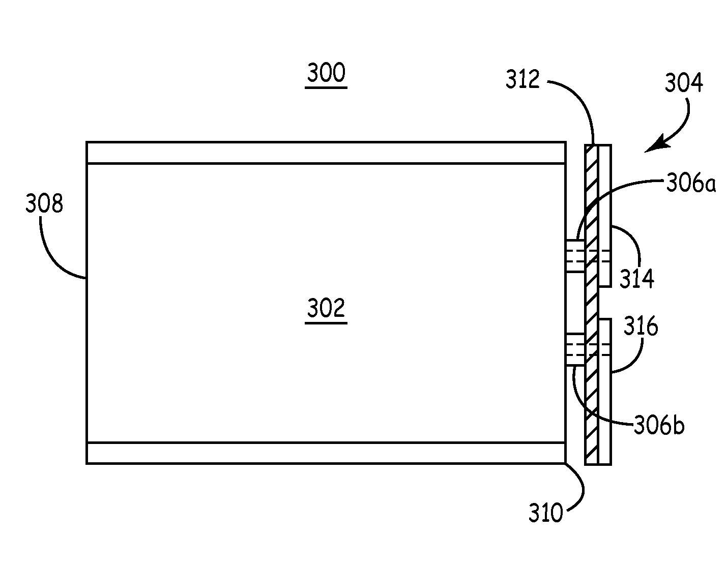
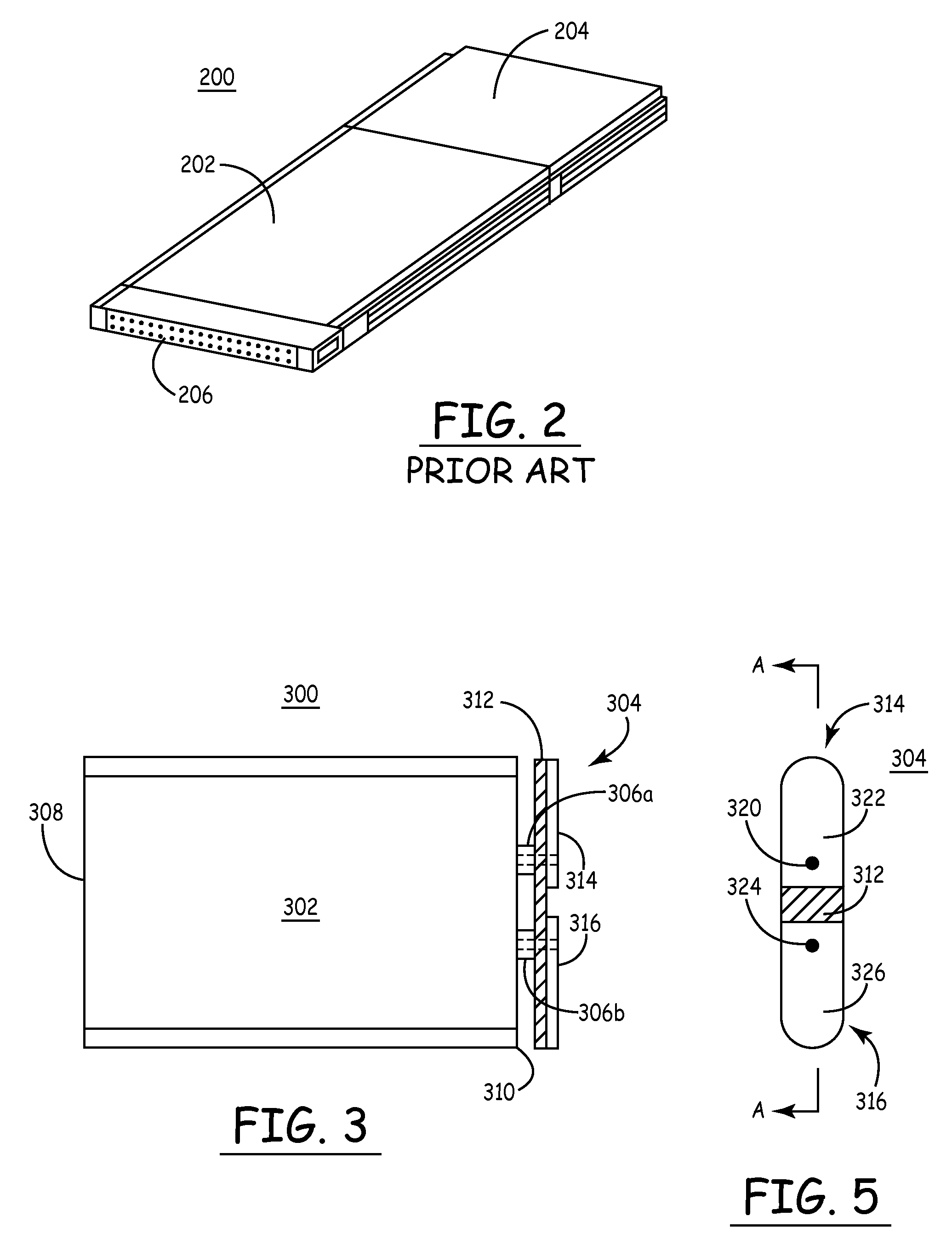
[0005]A wireless data communication card configured in accordance with an embodiment of the invention utilizes a compact and low profile RF antenna structure. The low profile design of the RF antenna structure enables the wireless data communication card to be completely enclosed within the housing of a computing device. The RF antenna structure does not protrude from the computing device, and provides compact overall appearance. Furthermore, the wireless data communication card is protected by the housing of the computing device.

Problems solved by technology

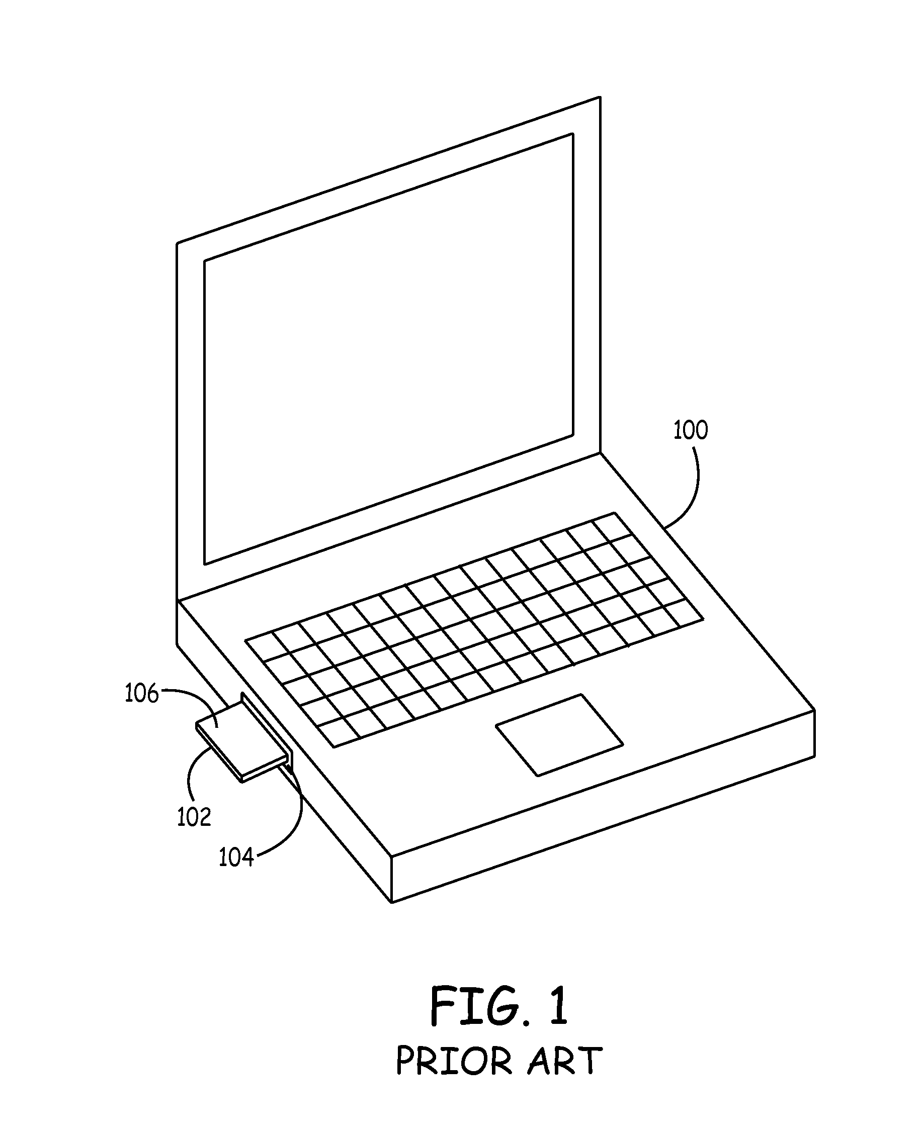
While this arrangement may result in adequate RF performance, the protruding wireless data communication card 102 is susceptible to tampering, damage, and inadvertent dislodging.

Method used


Image

  • Wireless data communication card with compact antenna
  • Wireless data communication card with compact antenna
  • Wireless data communication card with compact antenna

Examples


Embodiment Construction

[0020]The following detailed description is merely illustrative and is not intended to limit the invention or the application and uses of the invention. Furthermore, there is no intention to be bound by any expressed or implied theory presented in the preceding technical field, background, brief summary or the following detailed description.

[0021]The invention may be described herein in terms of functional and / or logical block components and various processing steps. It should be appreciated that such block components may be realized by any number of hardware, software, and / or firmware components configured to perform the specified functions. In addition, those skilled in the art will appreciate that the present invention may be practiced in conjunction with any number of data transmission protocols and that the devices described herein are merely practical example applications for the invention.

[0022]For the sake of brevity, conventional techniques related to wireless data communic...


PUM


Abstract

A wireless data communication card configured in accordance with an example embodiment of the invention includes a low profile antenna arrangement that does not protrude from the housing of the computing device when the wireless data communication card is inserted into the housing. The low profile design is achieved without compromising the radio frequency (“RF”) characteristics and performance of the wireless data communication card by tuning the antenna arrangement to account for conductive ground structure located within the housing of the computing device. In accordance with one practical embodiment of the invention, the wireless data communication card is compliant with IEEE Standard 802.11(b) and compliant with PCMCIA specifications.

Description

TECHNICAL FIELD[0001]The present invention relates generally to an interface tool that facilitates wireless data communication between computing devices. More particularly, the present invention relates to a wireless data communication card for a computing device such as a personal computer or a remote telemetry component for implantable medical devices (“IMDs”).BACKGROUND[0002]Computers and computing devices are becoming common appliances in homes, offices, medical facilities, schools, manufacturing plants, and elsewhere. Customized computing devices that are based upon conventional personal computer architectures are also being deployed to support specific applications, such as medical testing, remote data communication with IMDs, automotive diagnostics, and the like. Furthermore, wireless data communication with computing devices and computer networks is becoming increasingly common. Such wireless data communication requires data transmission in accordance with a specific data co...

Claims


Application Information

Patent Timeline
Patent Type & Authority Patents(United States)
IPC IPC(8): H04B1/38H04M1/00
CPCH04B1/3816H01Q1/2275H01Q1/2291H01Q9/40
Inventor NGHIEM, DAVIDSIMONETTE, PAUL T.SAZENSKI, RANDYJAENKE, MATTHEW G.TRAN, DAVID H.
Owner MEDTRONIC INC
Learn More