Self-leveling foot for an appliance

a self-leveling and foot technology, applied in the direction of machine supports, furniture parts, cleaning equipment, etc., can solve the problems of vibration, shake, limp, more serious consequences, etc., and achieve the effect of high resistance, simple and strong, and great capacity to mov

Inactive Publication Date: 2010-06-29
WHIRPOOL SA
View PDF8 Cites 43 Cited by
  • Summary
  • Abstract
  • Description
  • Claims
  • Application Information

AI Technical Summary

Benefits of technology

[0010]As a result of the drawbacks related to the structural complexity and fragility of the self-leveling foot defined in the prior art cited above, it is an object of the present invention to provide a type of foot which presents a simple and strong construction, with great capacity to withstand transversal forces between the upper and lower parts of the foot.
[0011]It is a further object of the invention to provide a self-leveling foot as defined above and which presents a dampening element that is capable to limit the relative vertical oscillations between the moving parts of the foot, in order to absorb the vibrations produced during the operational steps of the appliance seated thereon.
[0012]These and other objects of the present invention are achieved with the provision of a self-leveling foot, which comprises a base to be seated on any floor, in the ambient in which the appliance is installed, and a rod attached to the base and projecting upwardly therefrom. A tubular sleeve is slidably mounted and guided around the rod, being axially moveable in relation to the latter and having an upper portion mounted under the appliance and a lower portion seated on the upper end of an elastic element, generally a helical spring mounted around the rod, said elastic element having a lower end seated on the base. Thus, the elastic element transfers to the base a portion of the appliance weight associated with the respective sleeve seated on the elastic element, the rod functioning as a strong guide means for the tubular sleeve attached under the appliance, guaranteeing a high resistance for the foot to horizontal transversal forces exerted on the appliance, which can occur, for example, when the latter is forced to move, horizontally sliding on the floor.
[0013]In the proposed solution it may be also provided a dampening means mounted between the rod and the tubular sleeve, to apply a braking force to the relative axial movement between the rod and the tubular sleeve. Said braking force exerted by the dampening means provides an intense absorption of the vibrating energy transmitted from the appliance frame to the spring, guaranteeing the obtention of a necessary stabilizing function for the foot of the appliance.

Problems solved by technology

Nevertheless, even in the applications above, it is required from the user or installer to manually adjust the height of the feet as a function of the usual elevational differences of the floor, which operation requires special attention, besides being invariably uncomfortable and problematic, particularly when the appliance is installed in places that make difficult or impracticable the access to one or both rear feet.
When the washing machine feet have not their heights adjusted, the machine presents an unstable seating condition on the floor, making it “shake” or “limp” when submitted to even small forces produced by oscillating masses.
In this condition, the problem of vibration during the spinning operations makes even more serious the consequences of the unstable seating, as the machines seated in this way can intensely “limp” and vibrate during the spinning operations.
Said stronger vibrations are not generally absorbed by the suspension system of the moving parts of the appliance during determined operational steps, as it occurs when part of the load of clothes is unbalanced in the interior of the rotating basket, generating an excessive displacement of the moving parts.
When these vibrations are transmitted to an appliance seated on feet that are not appropriately adjusted in height, the consequences of the vibrations for the appliance frame are highly undesirable, producing noise, displacements and undesirable wear, and also risks of damage.
While allowing obtaining a self-leveling foot with great capacity of absorbing vibrations, the solution of patent U.S. Pat. No. 5,344,116 presents a complex and onerous construction, which limits the constructive possibilities of the base and transfers all the responsibility for the guidance of the relative vertical displacement between the lower and upper parts of the foot solely to the structure of the supporting spring and to the frictional displacement between the peripheral elastic element of the upper connecting element against the cylindrical inner wall of the housing defined in the base.
This prior art self-leveling foot has low resistance to transversal forces applied to the appliance.

Method used


Image

  • Self-leveling foot for an appliance
  • Self-leveling foot for an appliance
  • Self-leveling foot for an appliance

Examples


Embodiment Construction

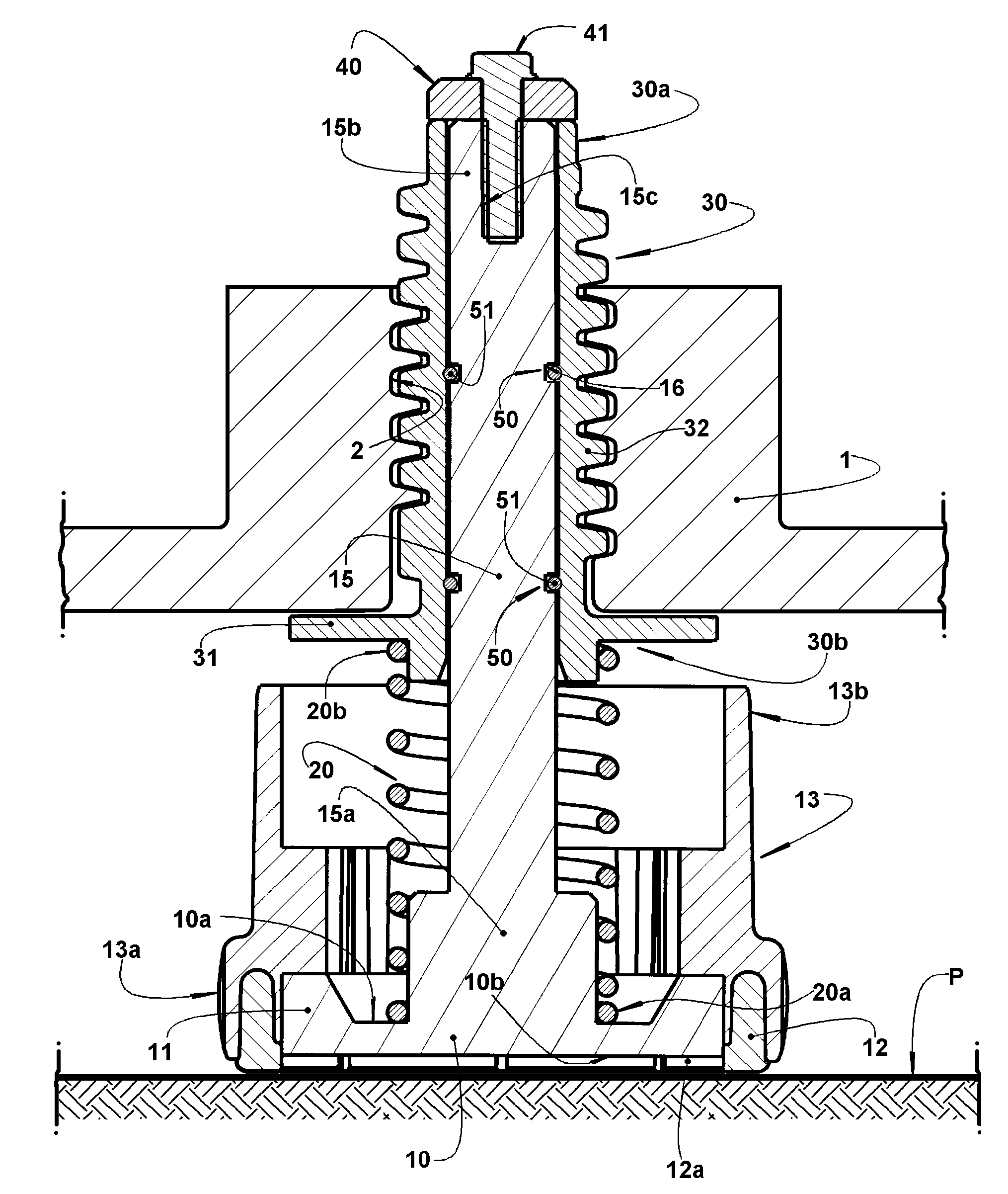
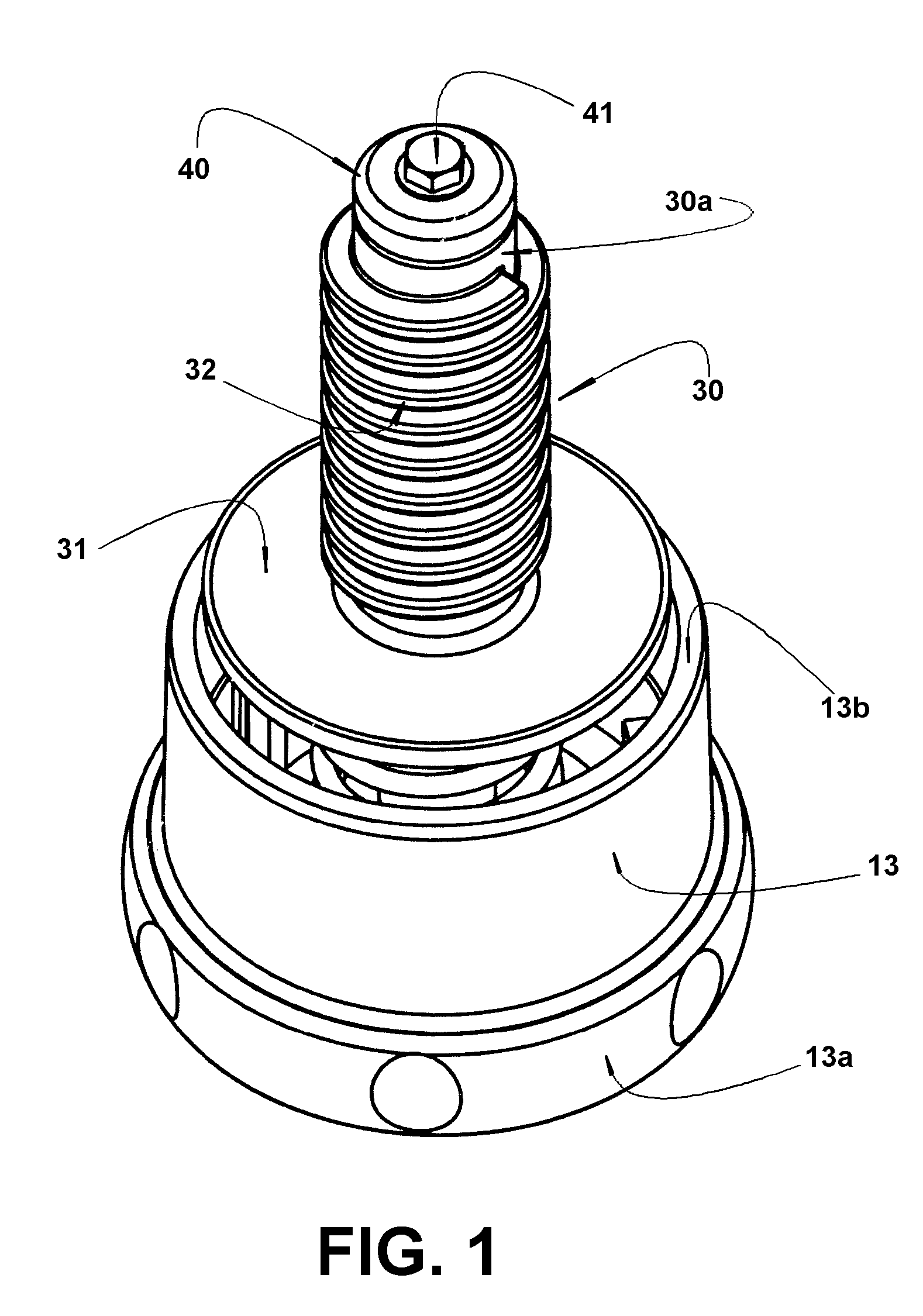
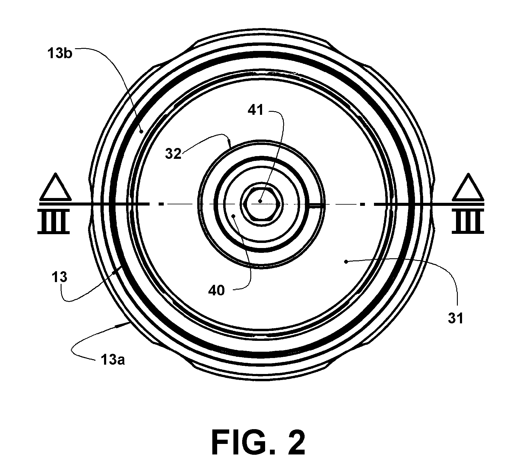
[0018]As already mentioned and illustrated in the enclosed drawings, the self-leveling foot object of the present invention is of the type to be mounted under a lower frame portion of an appliance such as, for example, the washing machines in which the machine cabinet presents a lower frame portion 1 with any adequate construction, which permits the fixation of a plurality of feet, generally in the number of four. The lower frame portion 1 can be defined, for example, by a flat plate or by plate portions affixed or incorporated to the appliance frame or cabinet in the mounting regions of the feet.

[0019]According to the invention, the self-leveling foot comprises a base 10 constructed in steel, plastic or other adequate material and which, in the illustrated embodiment, takes the form of a plate of circular contour, presenting an upper face 10a and a lower face 10b and incorporating an upper peripheral wall 11. It should be understood that the base 10 can present different regular an...


PUM


Abstract

A self-leveling foot for an appliance of the type that includes a base to be seated on a floor; a rod affixed to the base and projecting upwardly therefrom; an elastic element having a lower end seated on the base and a tubular sleeve, slidably mounted and guided around the rod, and having a lower portion seated on the upper end of the elastic element and an upper portion to be mounted under a lower frame portion of the appliance, so as to apply on the base, through the elastic element, a respective portion of the appliance weight. The foot of the present invention may further comprise a dampening means mounted between the parts of rod and tubular sleeve, so as to exert a braking force against the relative axial movement between said parts.

Description

FIELD OF THE INVENTION[0001]The present invention refers to a self-leveling and stabilizing foot to be connected under a lower portion of a frame or cabinet of an appliance such as, for example, a household appliance in the form of a washing machine. Although being particularly appropriate for washing machines, the foot object of the present invention can be also used in other appliances, such as dryers, refrigerators, and the like.PRIOR ART[0002]Different appliances, such as the white line household appliances, are directly seated on the floor by means of feet, generally four feet, mounted under a frame lower portion of the appliance.[0003]There are well known the feet of the fixed type or of the height-adjustable type, to compensate for irregularities of the floor, some models being also provided with rollers, with or without brakes, to facilitate the displacement of the appliance in determined situations.[0004]The known feet, particularly the adjustable ones, are generally adequa...

Claims


Application Information

Patent Timeline
Patent Type & Authority Patents(United States)
IPC IPC(8): F16M11/24
CPCA47L15/4253F16M7/00D06F39/125
Inventor DE TOLEDO, CARLOS EDUARDO BURATTOBRAZ, ADELCIODE OLIVEIRA, ANTONIOBARCHA, WLADIMIR ALEX MAGALHAESPEREIRA, DOUGLAS ALEX RESENDEMUNHOZ, ERICO DE OLIVEIRAOYAMA, JORGE
Owner WHIRPOOL SA
Why Eureka
Try Eureka