
Backlight unit and method for fabricating the same

a backlight unit and backlight technology, applied in the field of backlight units, can solve the problems of affecting the operation of the backlight unit, and the screen in front of the failed lamp will become significantly darker compared to the rest of the screen, so as to reduce the humming noise

Inactive Publication Date: 2010-06-29
LG DISPLAY CO LTD
View PDF10 Cites 3 Cited by
  • Summary
  • Abstract
  • Description
  • Claims
  • Application Information

AI Technical Summary

Benefits of technology

[0021]Accordingly, one advantage of the present invention is that it reduces the humming noise experienced when a dimmer control voltage is applied to an LCD.
[0022]Additional advantages of the invention will be set forth in the description that follows, and in part will be apparent from the description, or may be learned by practice of the invention. The advantages of the invention will be realized and attained by the structure pointed out in the written description and claims hereof as well as the appended drawings.
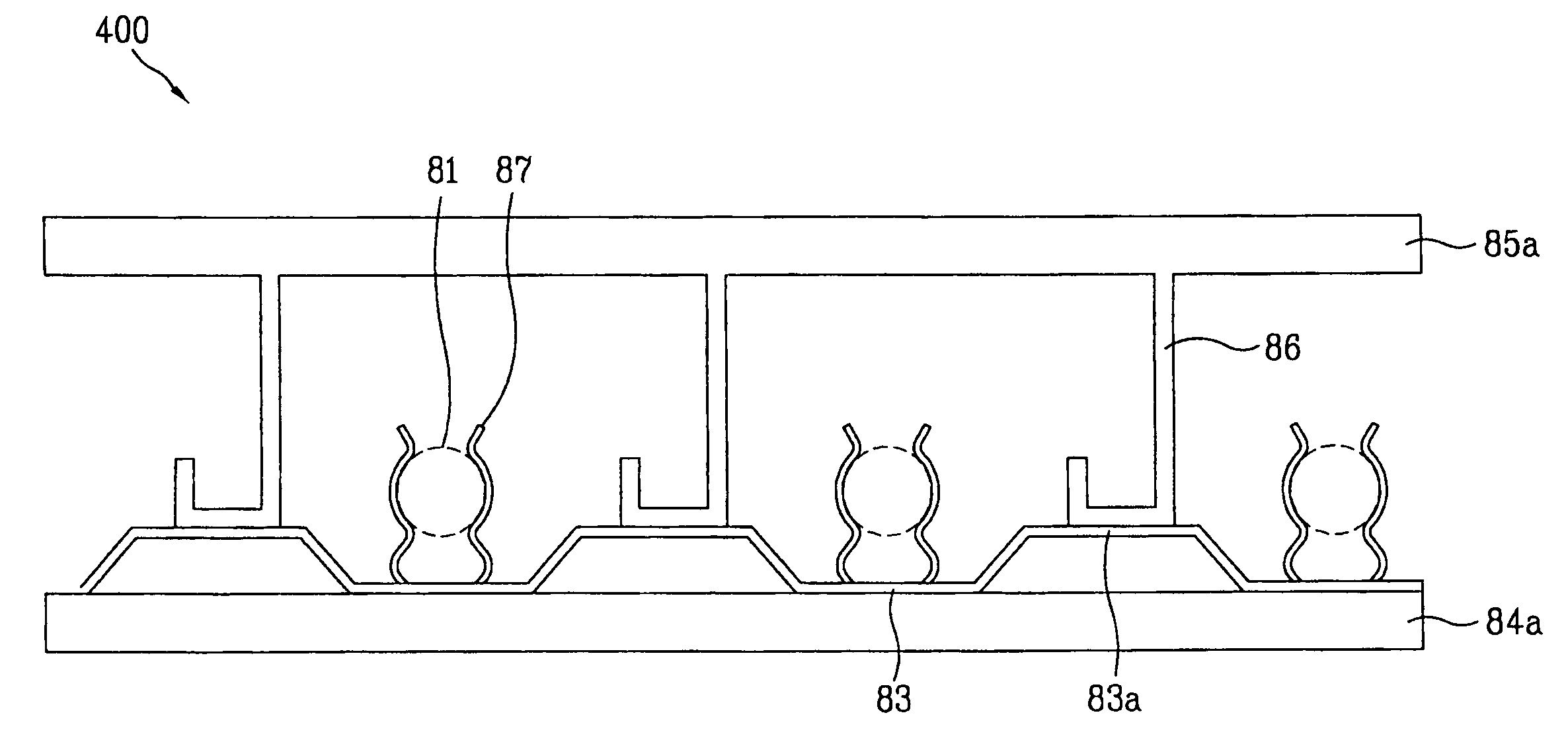
[0023]To achieve these and other advantages and in accordance with the purpose of the invention, the present invention involves a backlight unit. The backlight unit comprises a plurality of lamps; a first lower structure mounted at a first end of the lamps, the first lower structure having a first plurality of grooves, wherein each of the first plurality of grooves are disposed between the lamps; a first plurality of sound absorbing pads, wherein each of the first plurality of sound absorbing pads is disposed in one of the first plurality of grooves; a first plurality of common electrodes coupled to the first lower structure having the first plurality of sound absorbing pads disposed between the first plurality common electrodes and the first lower structure; and a first upper structure coupled to the first lower structure, wherein the first upper structure has a first plurality of ribs.
[0024]In another aspect of the present invention, the aforementioned and other advantages are achieved by a backlight unit, which comprises a plurality of lamps arranged over a bottom cover; first and second lower structures mounted at opposite ends of the lamps, respectively; common electrodes mounted on the first and second lower structures respectively, each of the common electrodes having elevated flat portions between adjacent lamps; and first and second upper structures respectively coupled to the first and second lower structures, each of the first and second upper structures having a plurality of ribs, wherein each rib has a bent flat portion.
[0025]In another aspect of the present invention, the aforementioned and other advantages are achieved by a method of fabricating a backlight. The method comprises forming a first lower structure having a plurality of first grooves; attaching a first plurality of sound absorbing pads to the first lower structure, wherein each of the first plurality of sound absorbing pads is disposed in one of the first plurality of grooves; attaching a first plurality of common electrodes to the first lower structure, wherein the first plurality of sound absorbing pads are disposed between the first lower structure and the common electrodes; providing a plurality of lamps; attaching an end of each of the plurality of lamps to a corresponding common electrode within the first plurality of electrodes; and attaching a first upper structure having a first plurality of ribs to the first lower structure, wherein attaching the first upper structure includes pressing the first plurality of ribs against the first common electrodes and the first sound absorbing pads.

Problems solved by technology

However, CRTs have disadvantages with regard to, for example, size and weight.
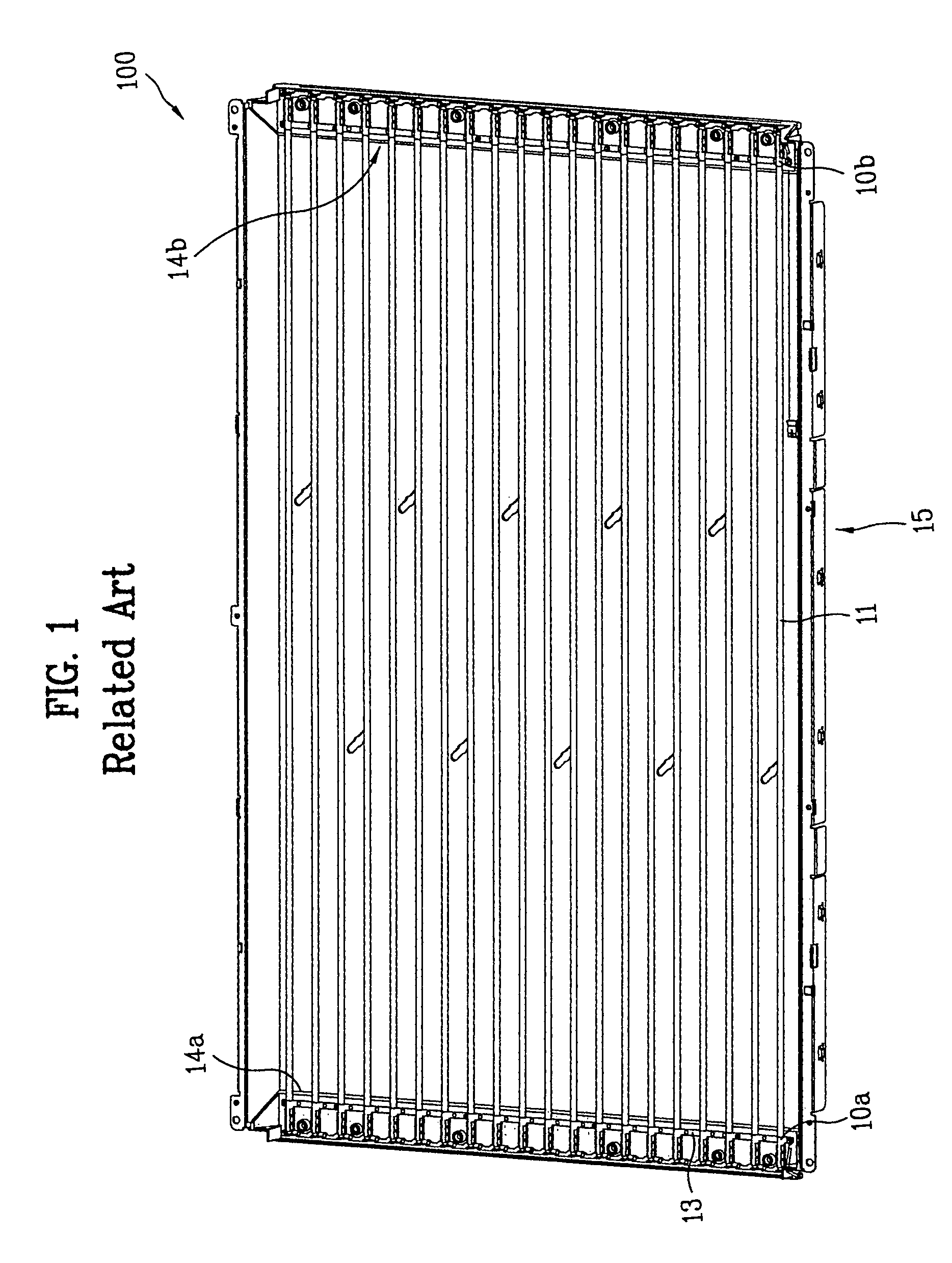
However, because LCDs having direct type backlight units, such as large sized monitors, TVs, or the like, have a longer time period of use and a greater number of lamps as compared to laptop computers, direct type backlight units have a higher rate of lamp failure than edge type backlights.
However, because the direct type has the plurality of lamps under the screen, if one lamp fails, the portion of the screen in front of the failed lamp will become significantly darker compared to the rest of the screen.
However, the repetitive application of AC power to the common electrodes 13 at such a frequency causes vibration to occur not only at the lamps, but also at the common electrodes having the power applied to them.

Method used


Image

  • Backlight unit and method for fabricating the same
  • Backlight unit and method for fabricating the same
  • Backlight unit and method for fabricating the same

Examples


Embodiment Construction

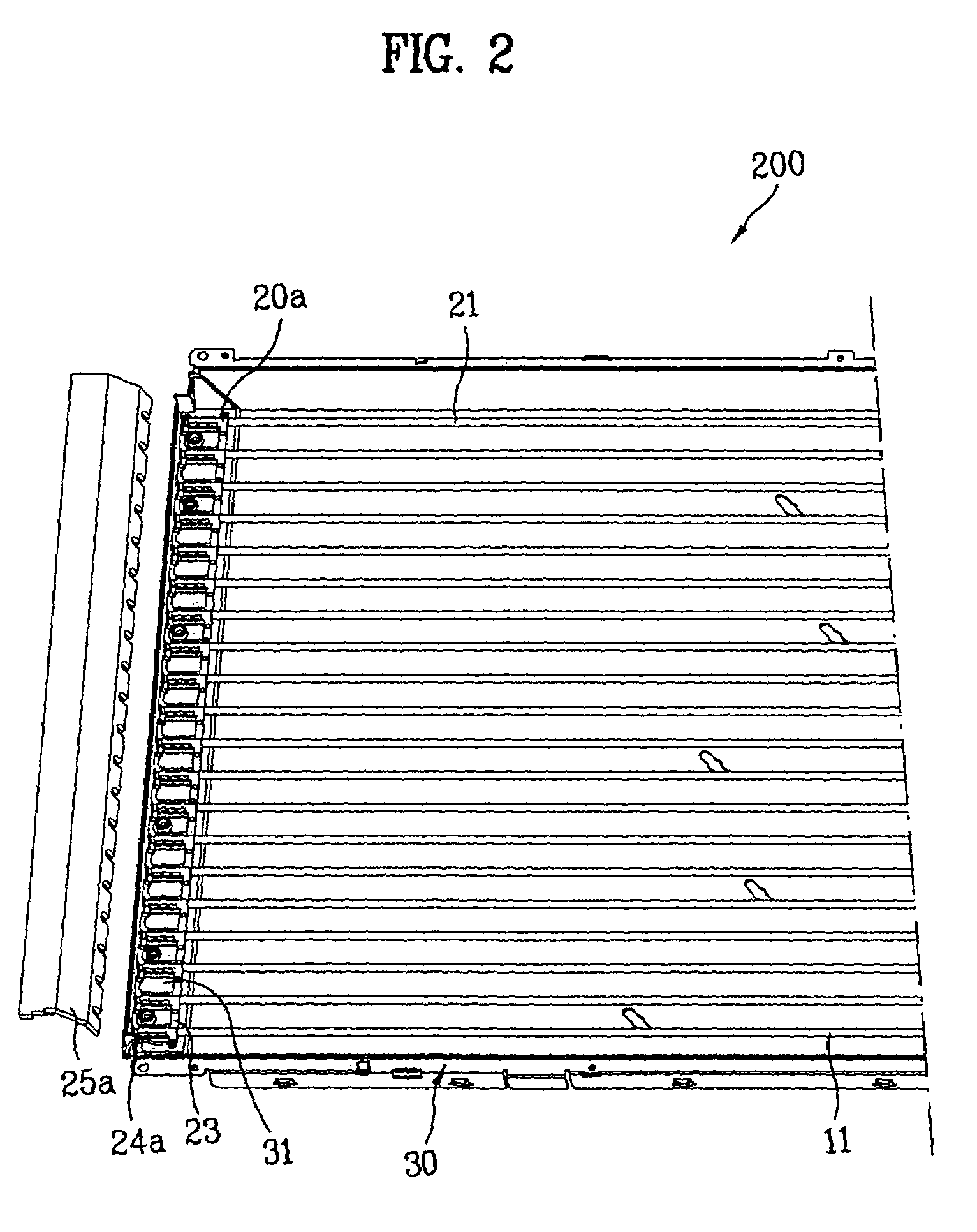
[0036]Referring to FIGS. 2, 3, and 4, the backlight unit 200 includes a plurality of lamps 21 arranged over a bottom cover 30 at regular intervals, each with a first external electrode 20a and a second external electrode 20b (not shown) at opposite ends of a tube, and common electrodes 23 having gripper type fastening portions 27 for fixedly securing the lamps 21 respectively and applying a voltage to the first and second external electrodes at the opposite ends of the lamps 21. Backlight unit 200 further includes a first lower structure 24a and a second lower structure (not shown) arranged under the opposite ends of the lamps 21 for seating the common electrodes 23 at the ends of the lamps, and a first upper structure 25a and a second upper structure (not shown) having a plurality of ribs 26 for holding down the common electrodes 23 over the first, and second lower structures.

[0037]The first lower structure 24a and the second lower structure include a groove 31 between adjacent lam...


PUM


Abstract

Disclosed is a backlight unit that is suitable for reducing humming noise that occurs when power is applied for dimming control. The present invention provides a backlight unit including a plurality of lamps arranged over a bottom cover, first and second lower structures respectively mounted at opposite ends of the lamps, the first and second lower structures having a groove between adjacent lamps, sound absorbing pads disposed within the grooves, common electrodes mounted on the first and second lower structures having the sound absorbing pads thereon respectively, and first and second upper structures respectively coupled to the first and second lower structures. The first and second upper structures have a plurality of ribs that press down on the common electrodes and sound absorbing pads.

Description

[0001]This application claims the benefit of the Patent Korean Application No. P2006-60527, filed on Jun. 30, 2006, which is hereby incorporated by reference as if fully set forth herein.BACKGROUND OF THE INVENTION[0002]1. Field of the Invention[0003]The present invention relates to a backlight unit and method for fabricating the same for a display. More particularly, the present invention relates to a backlight unit suitable for reducing humming noise that takes place during dimming adjustment of the backlight unit having external electrode lamps.[0004]2. Discussion of the Related Art[0005]The CRT (Cathode Ray Tube) has traditionally served as the basis for televisions, monitors, information terminals, etc. However, CRTs have disadvantages with regard to, for example, size and weight.[0006]Other display technologies have emerged, which address the size and weight problems associated with CRTs. Among these are Liquid Crystal Displays (LCD), which utilize an electro-optical effect; P...

Claims


Application Information

Patent Timeline
Patent Type & Authority Patents(United States)
IPC IPC(8): F21S4/00
CPCG02F1/133604H01J5/50G02F1/133608G02F2201/505G02F1/1335
Inventor KIM, KYOUNG SUBJANG, EUN SEOKHUO, DONG IM
Owner LG DISPLAY CO LTD
Learn More