Speed indication for pump condition monitoring

a technology of condition monitoring and speed indication, which is applied in the direction of piston pumps, positive displacement liquid engines, instruments, etc., can solve the problems of wiring back and sensing devices

Inactive Publication Date: 2010-06-29
ITT MFG ENTERPRISES LLC
View PDF6 Cites 54 Cited by
  • Summary
  • Abstract
  • Description
  • Claims
  • Application Information

AI Technical Summary

Benefits of technology

[0015]One advantage of the present invention is that it effectively eliminates the need for a Hall Effect or other suitable sensor and its associated wiring otherwise used to obtain the rotational speed of the pump.
[0016]According to the present invention, the apparatus may take the form of a pump or other suitable rotating equipment, consistent with that described herein. In this case, the self contained pump electrical equipment power supply or other suitable power supply may include a stationary stator within which magnets on the shaft rotate to produce AC power. The stationary stator is connected back to circuitry that rectifies and regulates the power for pump instrumentation and monitoring operations. Before one of the phases of AC power is rectified, it is directed through a zero crossing circuitry that identifies the instant the AC voltage crosses from negative to positive voltage. This zero crossing or identification circuit then triggers a square voltage wave pulse for each time the AC voltage crosses from negative to positive voltage.
[0017]Circuitry that is employed in many of the above mentioned known speed measurement approaches may be adapted and used to measure the period of square voltage wave pulse and calculate the speed of the pump or other rotating equipment that has the self contained pump electrical equipment power supply attached.
[0018]The method includes implementing the steps thereof via a computer program running in a processor or control module consistent with that described herein.

Problems solved by technology

The disadvantage for all of the above systems is that they require a sensing device and the wiring back to an indicator.

Method used


Image

  • Speed indication for pump condition monitoring
  • Speed indication for pump condition monitoring
  • Speed indication for pump condition monitoring

Examples


Embodiment Construction

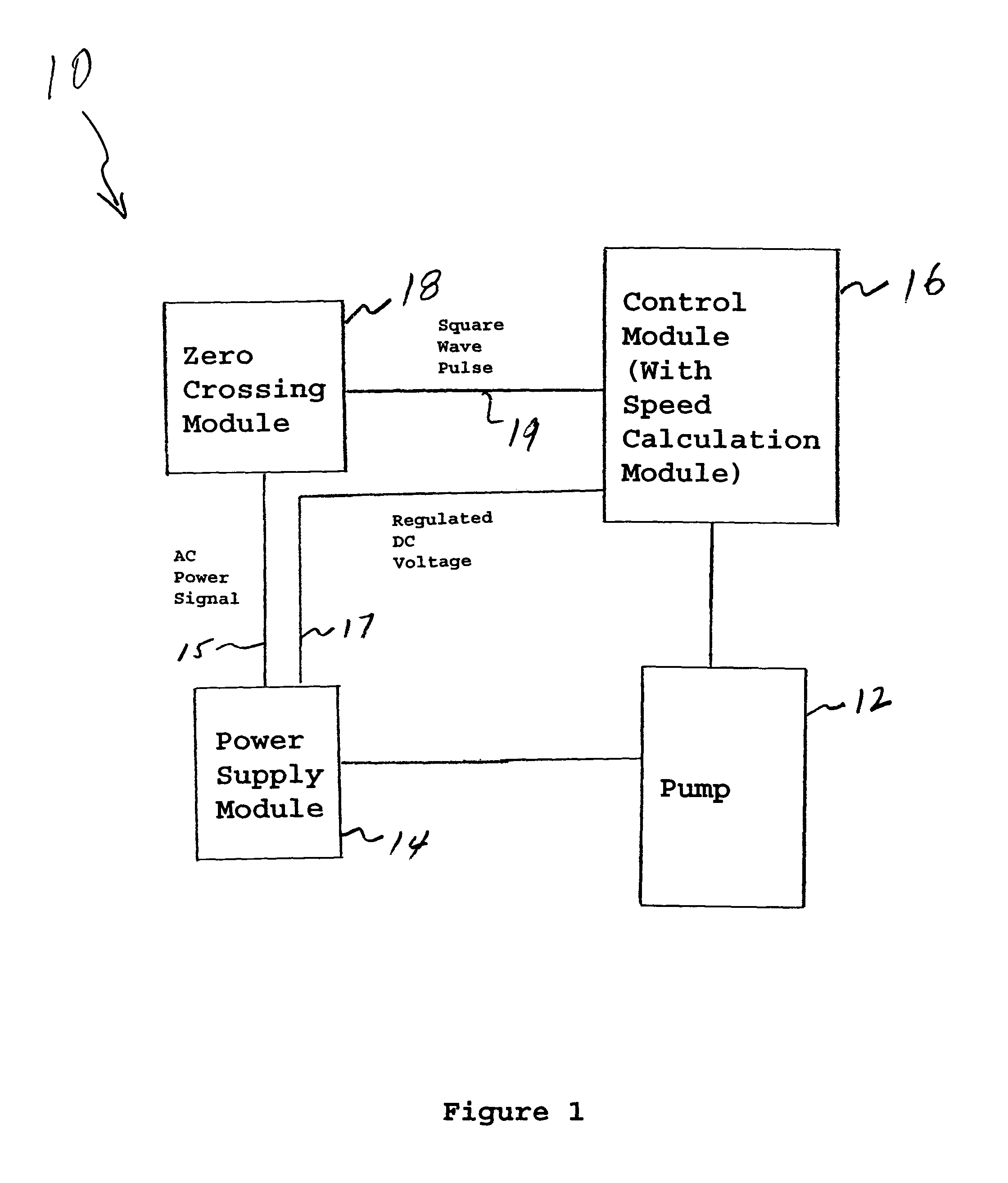
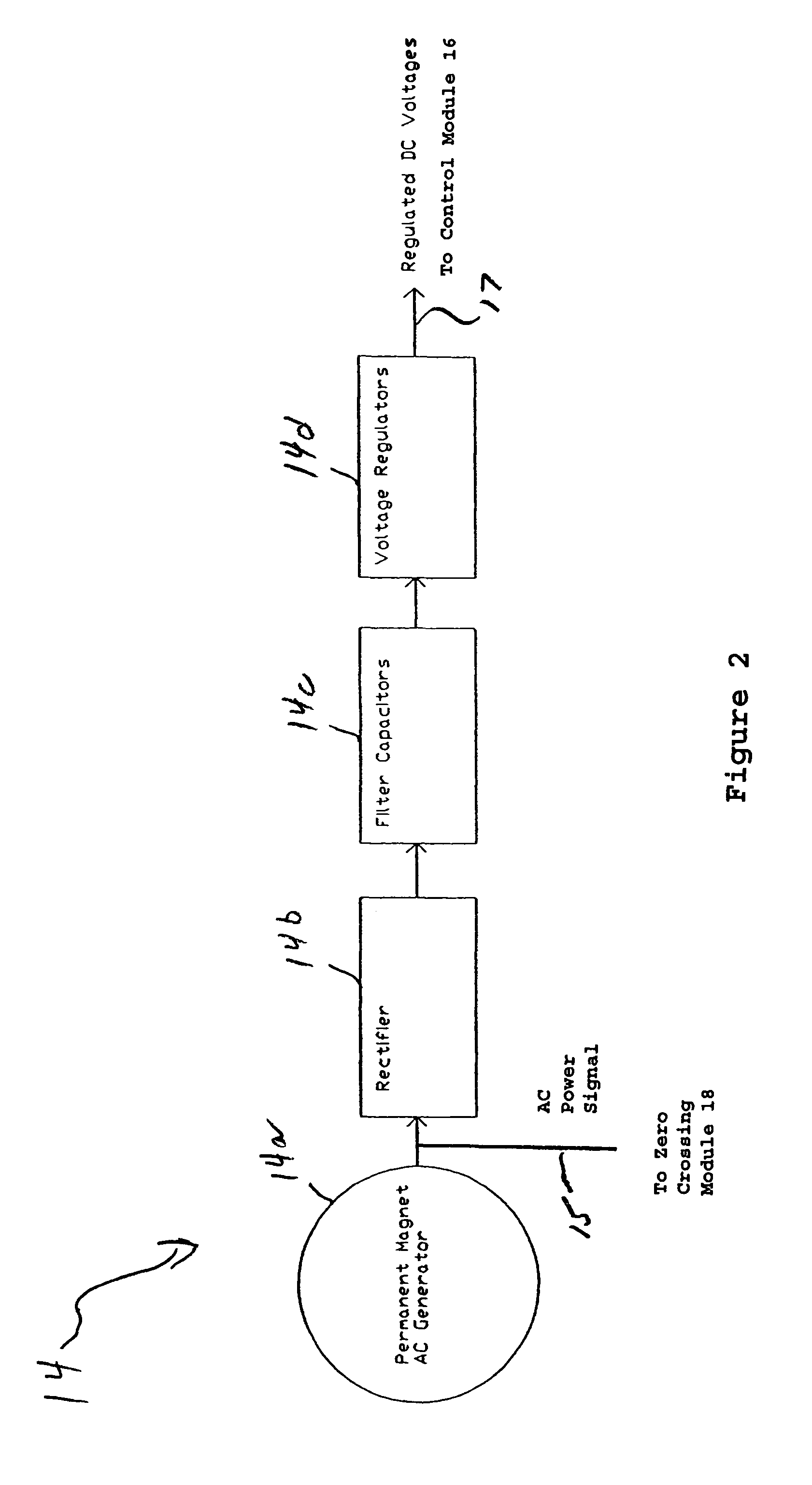
[0023]FIG. 1 shows, by way of example, a pumping system or other suitable rotating equipment generally indicated as 10, having a power supply module 14 and a module such as control module 16 for obtaining the rotational speed thereof. The present invention features a new and unique zero crossing circuit 18 that responds to one phase of AC power before being rectified from the power supply 14, identifies an instant of time the AC voltage crosses from one polarity to the other polarity and triggers a square wave pulse on line 19 for each instant time. In operation, the AC voltage from the power supply module 14 may be detected when it crosses from a negative polarity to a positive polarity, or vice versa. The control module 16 measures the period of the square wave pulse and calculates the speed of the pump 12 or other rotating equipment. The control module 16 may use the calculation of the speed of the pump 12 to control the basic operation of the pump 12, although the scope of the i...


PUM


Abstract

A method and apparatus are provided for obtaining the rotational speed of a pump system or other suitable rotating equipment having a self-contained pump electrical equipment power supply. The method features, before being rectified, directing one phase of AC power through a zero crossing circuit that identifies an instant of time the AC voltage crosses from one polarity to the other polarity and triggers a square wave pulse for each instant time. In operation, the AC voltage is detected when it crosses from a negative polarity to a positive polarity, or vice versa. The method also includes steps for measuring the period of the square wave pulse and calculating the speed of the pump or other rotating equipment.

Description

BACKGROUND OF THE INVENTION[0001]1. Technical Field[0002]The present invention generally relates to a pump system or other rotational equipment; and more particularly to a pump system or other rotational equipment having a module or other suitable device for performing pump condition monitoring.[0003]2. Description of Related Problem[0004]There are several commonly employed techniques to obtain the rotational speed of a pump or other rotating equipment:[0005]For example, a photo tachometer directs either a laser, infer red or visible light toward a reflective tape attached on the rotating shaft of a pump or other rotating equipment. A photo pickup in the photo tachometer senses the change in reflected light each time the tape passes. Speed in revolutions per minute is calculated from the period between the sensed light intensity changes.[0006]An inductive or capacitive switch may be placed near the key or keyway or the rotating shaft of the pump or other rotating equipment. As the k...

Claims


Application Information

Patent Timeline
Patent Type & Authority Patents(United States)
IPC IPC(8): G01P3/48
CPCG01P3/48G01P3/44
Inventor SABINI, EUGENE P.LORENC, JEROME A.HAUENSTEIN, KENNETH L.
Owner ITT MFG ENTERPRISES LLC
Why Eureka
Try Eureka