Reciprocating saw with fastening device for a saw blade

a technology of fastening device and saw blade, which is applied in the direction of metal sawing device, power driven reciprocating saw, manufacturing tools, etc., can solve the problems of time-consuming and laborious changing tools, and it is not possible to prevent the locking sleeve from loosening by itself, so as to eliminate the time-consuming rotation of the locking sleeve

Inactive Publication Date: 2010-07-06
ROBERT BOSCH GMBH
View PDF15 Cites 19 Cited by
  • Summary
  • Abstract
  • Description
  • Claims
  • Application Information

AI Technical Summary

Benefits of technology

[0006]More particularly, it is an object of the present invention to provide a reciprocating saw whose saw blade can on the one hand be securely attached and on the other hand can be quickly replaced.
[0008]The present invention is based on the concept of providing a spring-loaded locking element that can be moved between a release position and a locked position. In the locked position, the locking element attaches the saw blade to the fastening device and thus to the lifter rod in a form-locked fashion. This simply and securely prevents an axial movement of the saw blade. Because the locking element is spring-loaded toward the saw blade, this urges the locking element to assume the locked position.
[0009]At a predetermined position, the locking element automatically engages in detent fashion with the saw blade so that the saw blade is secured in the fastening device in captive fashion. This makes it possible to advantageously eliminate the time-consuming rotation of the locking sleeve. By contrast with a locking sleeve, the locking element of the reciprocating saw according to the present invention is advantageously prevented from loosening by itself due to the oscillations occurring during operation of the jigsaw.
[0017]It is advantageous if the saw blade is provided with a longitudinal slot between its fastening end and the recess for accommodating the locking element. This longitudinal slot permits the saw blade to pass by the actuated release button in the axial direction without colliding with the release button. To this end, the diameter of the release button is selected to be narrower than the width of the longitudinal slot. Naturally, the locking element must be dimensioned in such a way that the saw blade equipped with the longitudinal slot cannot be moved past the locking element when the locking element is situated in the recess.
[0019]Preferably, the fastening device includes a housing comprised of two plastic half-shells. These half-shells have the capacity to engage with each other in detent fashion. The inside of the housing accommodates an insert piece made of metal, preferably steel, which encloses the saw blade on both of its broad sides, thus preventing a rotation of the saw blade inside the fastening device. The insert piece advantageously rests against both broad sides of the saw blade.
[0020]In order to produce a form-locked connection between the fastening device and the lifter rod, a connecting piece is advantageously provided, which is attached to the lifter rod. The two half-shells embrace this connecting piece and thus lock the fastening device in relation to the lifter rod. Such an embodiment of the fastening device functions with a very small number of components and is also quick to assemble.

Problems solved by technology

The disadvantage of the known reciprocating saw is that changing tools is time-consuming because it is necessary to rotate the locking sleeve.
In addition, it is not possible to prevent the locking sleeve from loosening by itself due to the oscillations occurring during operation of the jigsaw.

Method used


Image

  • Reciprocating saw with fastening device for a saw blade
  • Reciprocating saw with fastening device for a saw blade
  • Reciprocating saw with fastening device for a saw blade

Examples


Embodiment Construction

[0035]In the figures, parts that are the same and those that are functionally equivalent have been provided with the same reference numerals.

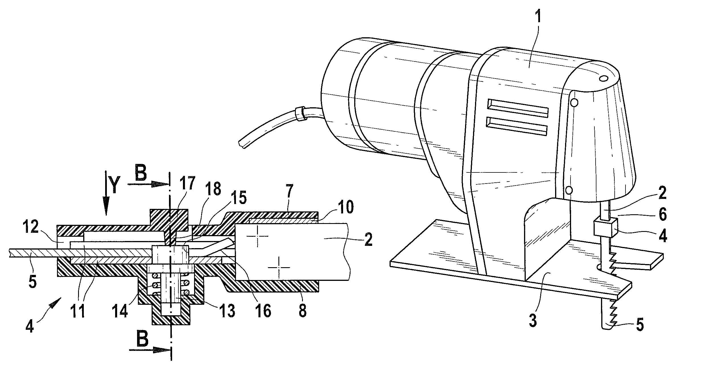
[0036]FIG. 13 shows a jigsaw 1 embodied in the form of a hand-guided power tool, equipped with a flat lifter rod 2 and a sliding plate 3. The jigsaw 1 has a fastening device 4 for a jigsaw blade 5. The fastening device 4 is attached to the end 6 of the lifter rod 2.

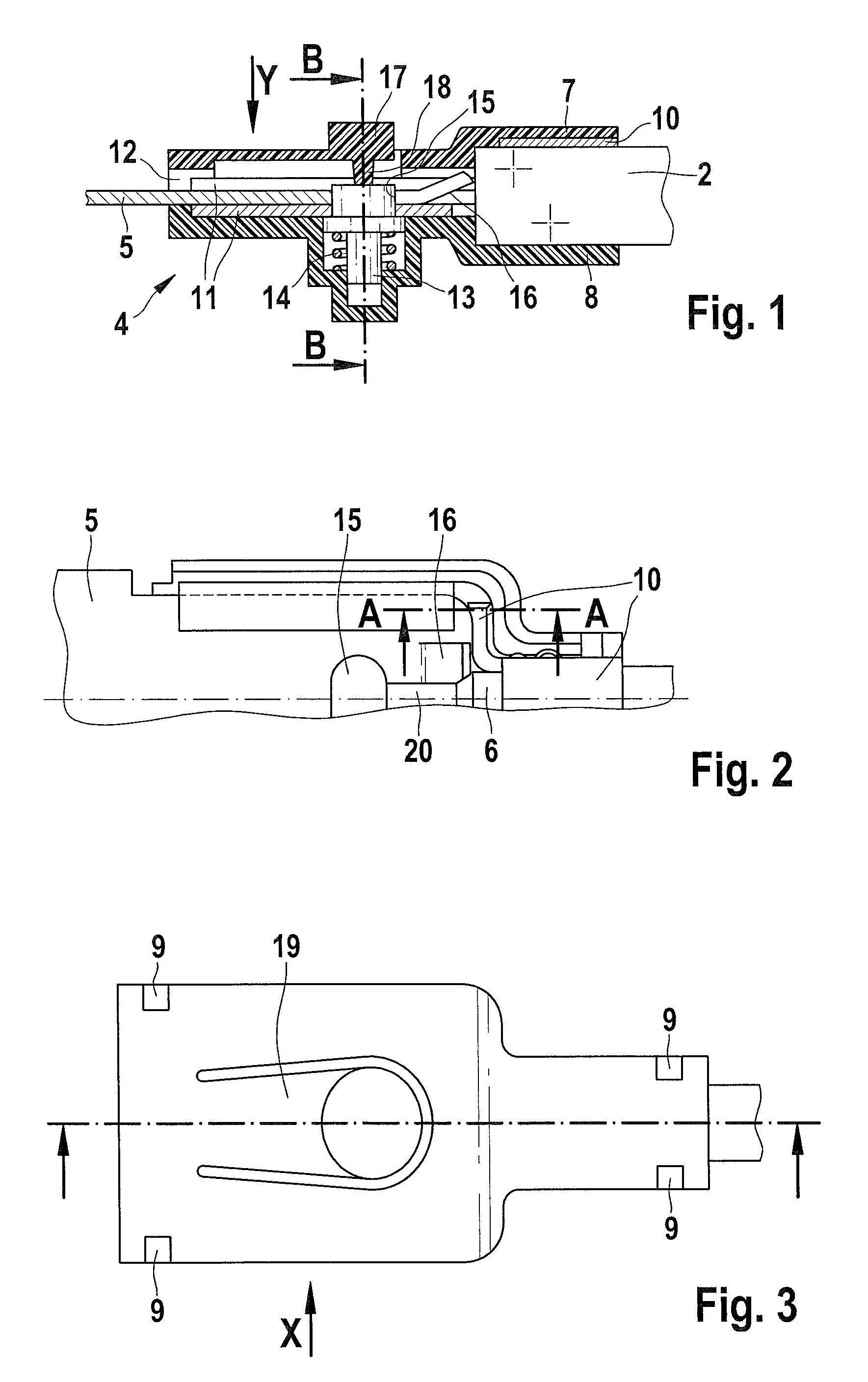
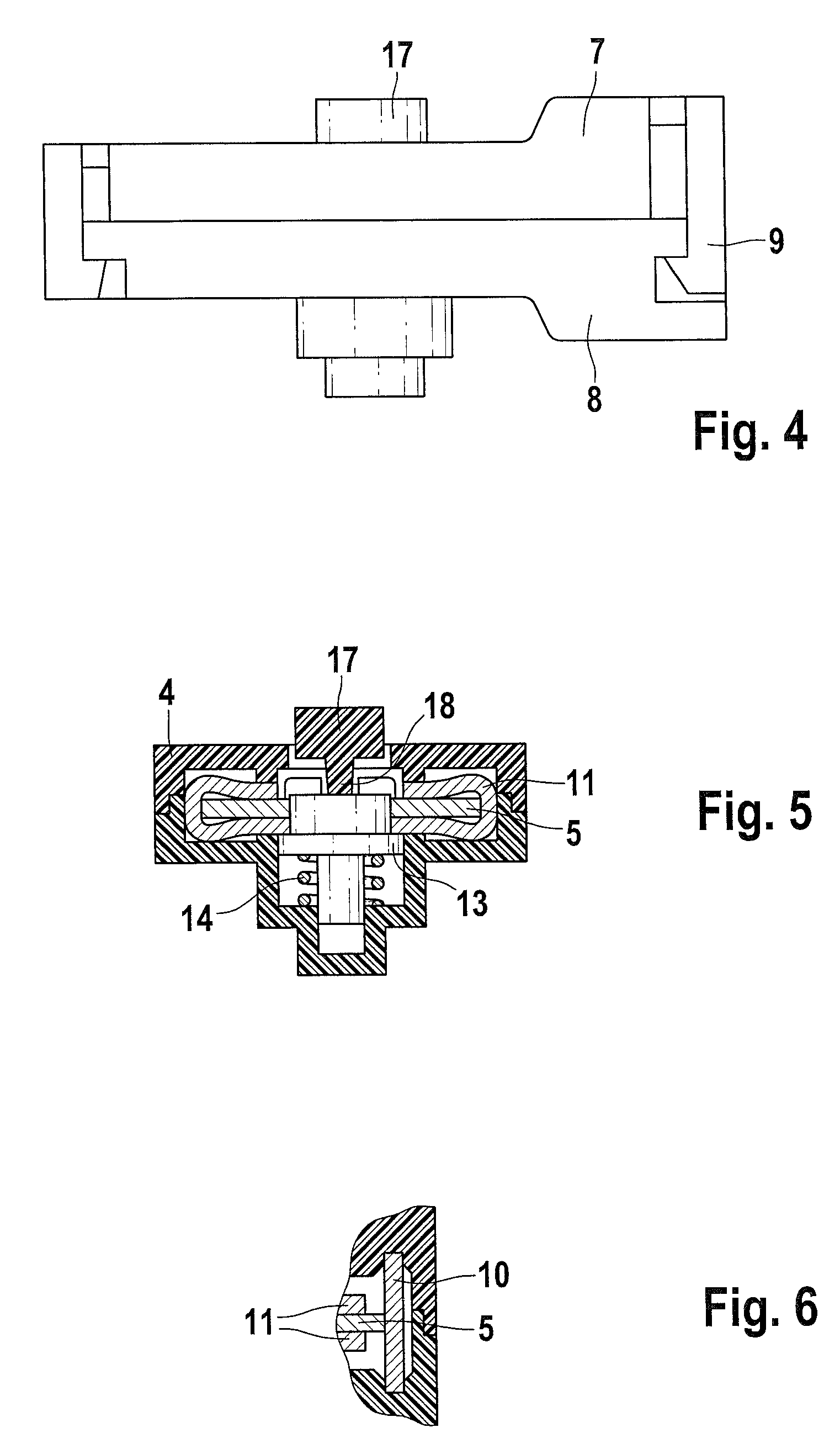
[0037]FIGS. 1 through 6 show a first embodiment of a fastening device 4. FIGS. 10 through 12 show a second embodiment of the invention.

[0038]As is clear from FIG. 1, the fastening device 4 has a housing comprised of a first housing half-shell 7 and a second housing half-shell 8. Both of the housing half-shells 7, 8 are composed of plastic and are attached to each other in detent fashion by detent means 9 that are shown in FIG. 3. The housing half-shells 7, 8 enclose a connecting piece 10, which is riveted to the lifter rod 2 that can move back and forth in the axial direction. As is ...


PUM

PropertyMeasurementUnit
spring forceaaaaaaaaaa
axial movementaaaaaaaaaa
timeaaaaaaaaaa

Abstract

A reciprocating saw has a saw blade, a fastening device provided for the saw blade and holding the saw blade in a non-rotating fashion, a reciprocating lifting rod having a free end supporting the fastening device, a locking element provided for axially fixing the saw blade in the fastening device, and having an adjusting spring that acts in a direction of the saw blade, wherein the locking element is movable between a release position and a locked position and holds the saw blade in the locked position in a form-locked fashion.

Description

CROSS-REFERENCE TO A RELATED APPLICATION[0001]The invention described and claimed hereinbelow is also described in German Patent Application DE 102005063015.4 filed on Dec. 30, 2005. This German Patent Application, whose subject matter is incorporated here by reference, provides the basis for a claim of priority of invention under 35 U.S.C. 119(a)-(d).BACKGROUND OF THE INVENTION[0002]The present generally relates to reciprocating saws. More particularly, it relates to a reciprocating saw with a fastening device for a saw blade.[0003]DE 32 471 78 C2 has disclosed a jigsaw with a fastening device for a flat jigsaw blade. The known fastening device includes a rotating element that is affixed to a lifter rod and is provided with an external thread onto which a locking sleeve equipped with a through opening for a saw blade shaft can be screwed. In order to insert the jigsaw, the locking sleeve must be rotated until the shaft of the jigsaw blade can be inserted through the through opening...

Claims


Application Information

Patent Timeline
Patent Type & Authority Patents(United States)
IPC IPC(8): B27B19/02
CPCB23D51/10Y10T279/17786B23D51/08
Inventor RAKACZKI, JANOS
Owner ROBERT BOSCH GMBH
Why Eureka
Try Eureka