Fungo batting assistance machine

a fungus and batting technology, applied in the field of apparatus and machinery, can solve the problems of inability to adjust the height and trajectory of the ball toss, the inability to provide an outside power source, and the bulkyness of the machine, and achieve the effect of rapid release of such potential spring energy

Inactive Publication Date: 2010-07-06
KOSJER MARCUS
View PDF23 Cites 5 Cited by
  • Summary
  • Abstract
  • Description
  • Claims
  • Application Information

AI Technical Summary

Benefits of technology

[0006]Also, in a preferred embodiment, the forwardly elongated “C” channel cradle comprises hingedly interconnected forward and rearward sections, such configuration facilitating rearward pivoting and folding of the cradle's forward section for purposes of compact storage and transport of the machine.
[0011]Where the spring means comprises the preferred helical rarefaction spring, spring tension adjustment means are preferably further provided for facilitating adjustability of the mechanism's ball striking force. A preferred spring tension adjusting means will be described in greater detail in the Detailed Description which follows.
[0014]While the pawl arm is pivotally moved to its trip arm carrying position, the distal end of the pawl arm preferably underlies an undersurface of the rearward end of the trip arm. Upon upward pivotal movement of the pawl arm toward its trip arm releasing position, the distal end of the pawl arm may advantageously clear the extreme rearward or distal end of the trip arm, releasing the trip arm.
[0017]In operation of the instant inventive fungo batting assistance machine, at least a first baseball or softball, and preferably a plurality of such balls, are placed in a forwardly extending series within the machine's ball cradle. Upon such ball placement, a rearmost ball preferably rearwardly rolls to a position overlying the ball cradle's ball percussion port. Thereafter, an operator, using his or her left or right foot, may press downwardly upon the actuation lever. Such downward driving motion upwardly pivotally moves the machine's pawl arm. Such upward pivotal motion of the pawl arm progressively upwardly pivots the machine's trip arm and simultaneously downwardly pivots the machine's hammer against the ball driving spring means. Accordingly, the kinetic energy of the operator's downwardly driven foot is temporarily stored as potential energy within the spring means. Upon progression of such pivotal motion, the extreme distal or forward end of the pawl arm eventually slidably clears the extreme distal or rearward end of the trip arm, allowing for the rapid release of such potential spring energy. Upon such release, the preferred ball driving spring drives the hammer upwardly through the ball percussion port and against the ball, driving the ball into the air for fungo batting.

Problems solved by technology

However, such machines typically are bulky, cumbersome, and mechanically complex.
Also, such machines typically undesirably require the provision of an outside power source such as alternating current electricity.
Also, such machines typically lack any capacity for adjustments of ball toss height and trajectory, and such machines often lack a sufficiently large ball magazine or ball feeder.

Method used


Image

  • Fungo batting assistance machine
  • Fungo batting assistance machine
  • Fungo batting assistance machine

Examples


Embodiment Construction

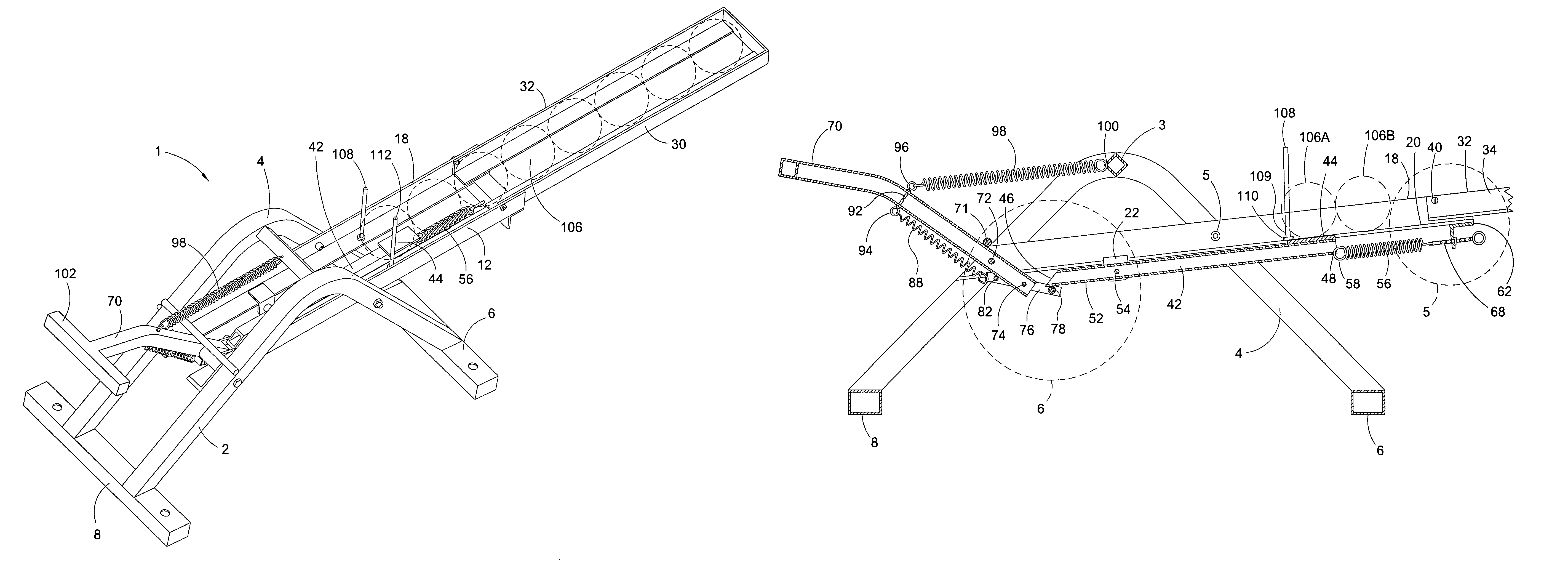
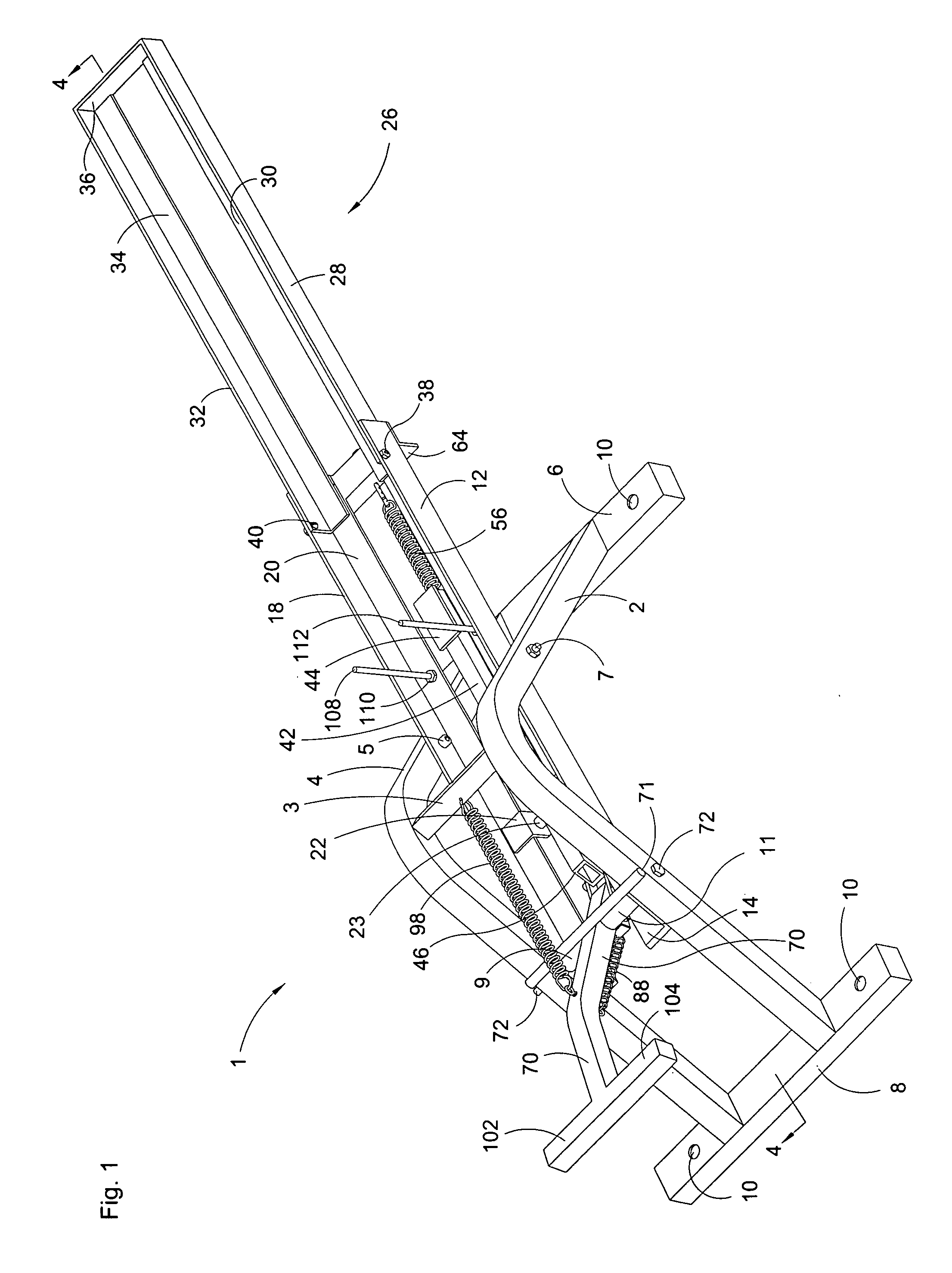
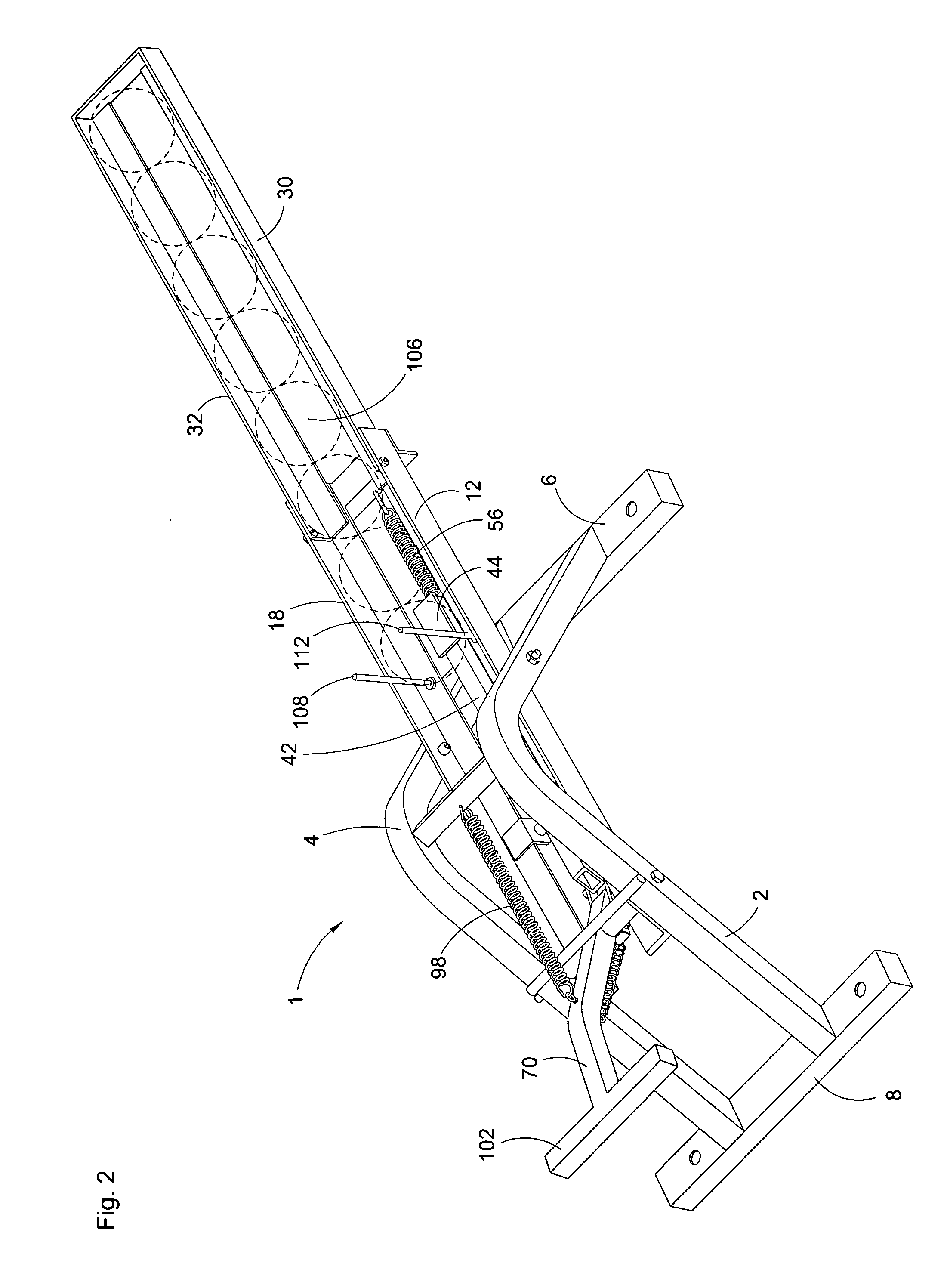
[0027]Referring now to the drawings, and in particular to FIG. 1, a preferred embodiment of the instant inventive fungo batting assistance machine is referred to generally by Reference Arrow 1. The machine 1 preferably comprises a frame which includes a front base member 6 and a rear base member 8. The frame 1 preferably further comprises a right “A” member 2 and a left “A” member 4, the lower ends of the legs of such “A” members 2 and 4 being fixedly welded to the base members 6 and 8. Further preferred frame components comprise a spring anchoring cross member 3 and a pivot stopping crossing member 71. The frame also preferably further comprises right and left longitudinally extending “L” beam members 12 and 18, such “L” beams being fixedly attached to “A” members 2 and 4 by nut and bolt combinations 5 and 7, and by a laterally extending pivot pin 72. Preferably, the outer ends of the base members 6 and 8 of the frame include vertically extending ground stake receiving apertures 10...


PUM


Abstract

A fungo batting assisting machine having a frame; a cradle mounted upon the frame, the cradle having a ball percussion port; a hammer; a first pivot joint interconnecting the hammer and the frame so that the hammer may move between a spring energy position underlying the ball percussion port and a ball driving position overlying the spring energy position; a ball driving spring normally positioning the hammer between its spring energy and ball driving positions; a trip arm extending from the hammer; a pawl arm; a second pivot joint interconnecting the pawl arm and the frame so that the a pawl arm may move between a trip arm carrying position and a trip arm releasing position; and an actuation lever extending from the pawl arm.

Description

FIELD OF THE INVENTION[0001]This invention relates to apparatus and machinery which is adapted for assisting in baseball or softball fielding practice. More particularly, this invention relates to such apparatus or machinery which is specially adapted for performing ball tosses for fungo batting.BACKGROUND OF THE INVENTION[0002]Ball tossing fungo batting assistance machines are known. However, such machines typically are bulky, cumbersome, and mechanically complex. Also, such machines typically undesirably require the provision of an outside power source such as alternating current electricity. Also, such machines typically lack any capacity for adjustments of ball toss height and trajectory, and such machines often lack a sufficiently large ball magazine or ball feeder.[0003]The instant inventive fungo batting assistance machine overcomes the drawbacks and deficiencies discussed above by providing a mechanically simple machine which is capable of repeatedly tossing a series of base...

Claims


Application Information

Patent Timeline
Patent Type & Authority Patents(United States)
IPC IPC(8): F41B3/03
CPCA63B69/0002A63B69/407A63B2069/0011A63B2069/401A63B2210/50F41B3/03F41B7/00
Inventor KOSJER, MARCUS
Owner KOSJER MARCUS
Why Eureka
Try Eureka