Electrical connector with regulating portion for regulating elastic deformation of terminal

a technology of elastic deformation and electric connector, which is applied in the direction of electrical equipment, coupling contact components, printed circuits, etc., can solve the problems of terminal falling off, affecting the regulating step position, and the bottom wall portion may not obtain sufficient strength, so as to achieve sufficient strength and expand the dimension of the regulating wall portion

Active Publication Date: 2010-07-06
HIROSE ELECTRIC GROUP
View PDF11 Cites 21 Cited by
  • Summary
  • Abstract
  • Description
  • Claims
  • Application Information

AI Technical Summary

Benefits of technology

[0023]In the present invention, when the mating connector is extracted, the elastic deformation of the fitting portion is regulated by the engagement of the regulating surface and the engaging portion, and the elastic deformation of the fitting portion is continuously regulated while the mating connector is extracted. Accordingly, it is possible to prevent the terminal of the connector from coming off.
[0024]According to the present invention, it is possible to enlarge dimensions of the regulating wall portion without enlarging a size of the connector. Thus, an area of the regulating surface engaging with the engaging portion can be larger. As a result, the engaging portion can engage with the regulating wall portion securely. Thus, it is possible to prevent the terminal of the connector from coming off sufficiently even in the case that the engaging portion varies a positioning thereof due to a manufacturing error or an assembling error.
[0025]In the present invention, the regulating wall portion of the housing extends in the connecting direction of the connectors. Accordingly, the regulating wall portion can be formed by removing a mold from an opening where the mating connector is connected. Thus, it is unnecessary to open a hole in a bottom wall portion of the connector for removing the mold, and the bottom wall portion can obtain a sufficient strength. Furthermore, when the connector is mounted on a circuit board, the bottom wall portion prevents an electrical conduction between the terminal and the circuit board, so that an electric property is not deteriorated.

Problems solved by technology

As a result, when a manufacturing error or an assembling error occurs, the engaging protrusion may not reach the position right under the regulating step portion when the terminal deforms elastically as the connector is connected to the mating connector.
In this case, the terminal may come off due to a failure to engage the engaging protrusion with the regulating step portion in the connecting direction of the connectors.
As a result, the bottom wall portion may not obtain a sufficient strength.
Furthermore, when the connector is mounted on a circuit board, an electrical conduction therebetween may occur due to a narrow space.
Consequently, an electric property may be deteriorated.

Method used


Image

  • Electrical connector with regulating portion for regulating elastic deformation of terminal
  • Electrical connector with regulating portion for regulating elastic deformation of terminal
  • Electrical connector with regulating portion for regulating elastic deformation of terminal

Examples


first embodiment

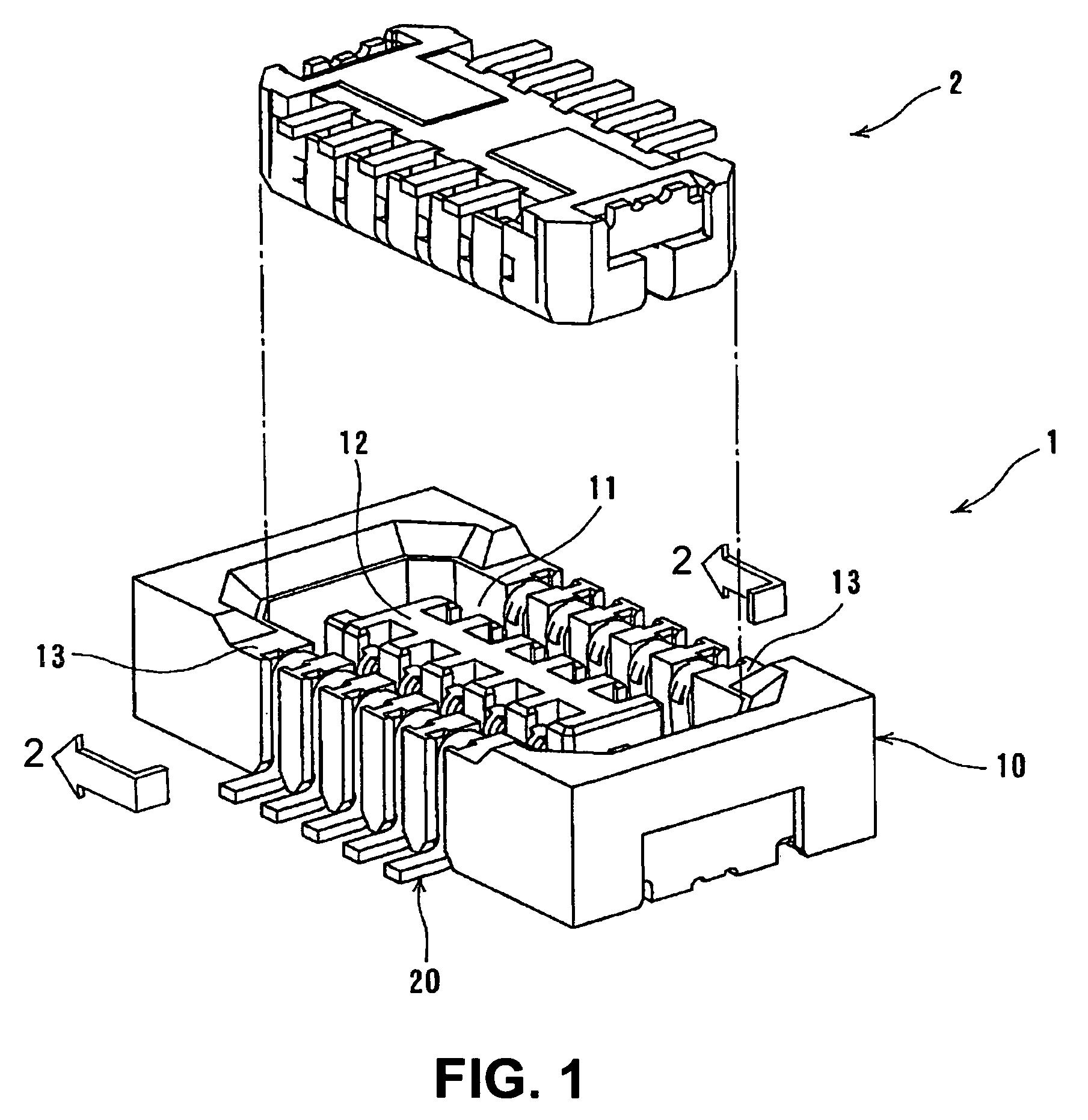
[0036]FIG. 1 is a perspective view showing an electrical connector 1 (connector) and a mating connector 2 to be connected thereto according to a first embodiment of the present invention.

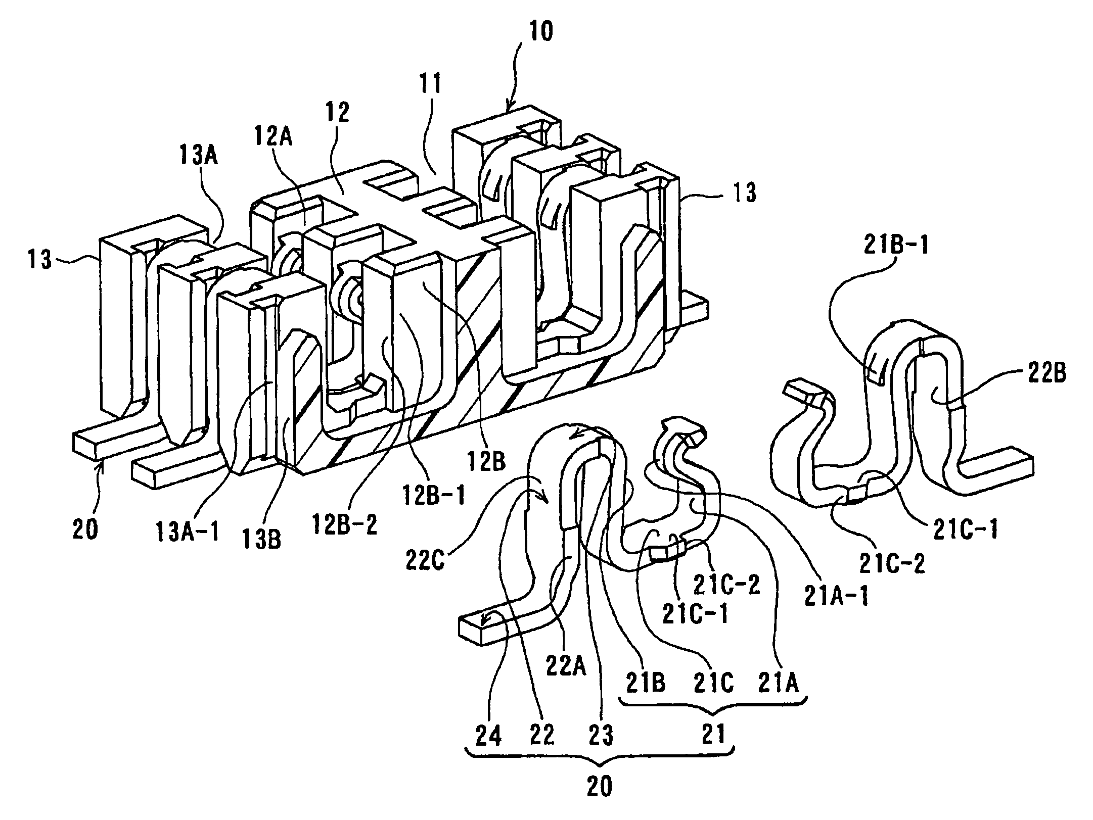
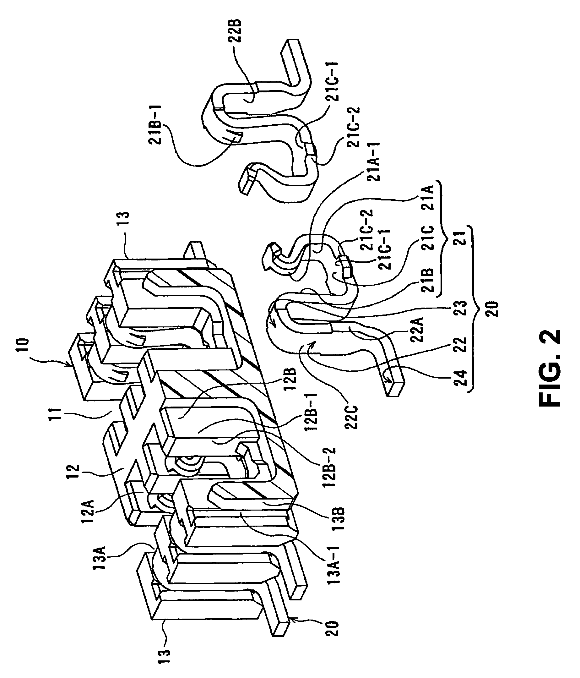
[0037]The connector 1 includes a housing 10 with an approximate rectangular solid shape and made of a synthetic resin; and a plurality of terminals 20 aligned and held in the housing 10. The housing 10 includes a receptacle recess portion 11 inside a circumference wall thereof for connecting the mating connector 2; and a central wall 12 having an approximate rectangular solid shape and located insularly at a central portion of the receptacle recess portion 11. Accordingly, the receptacle recess portion 11 is formed by an inner surface of the circumference wall, an outer circumference surface of the central wall 12, and an inner surface of a bottom wall of the housing 10. Two wall portions of the circumference wall of the housing 10 facing each other and extending in a longitudinal direction are form...

second embodiment

[0065]In the second embodiment, a basic structure of the connector 1 is the same as the connector 1 in the first embodiment. Accordingly, differences from the first embodiment will be mainly explained. The same reference numerals as the first embodiment denote the same components, respectively, and explanations thereof are omitted.

[0066]FIG. 5 is a sectional view showing a partial view of the connector 1 in the connecting direction of the connectors taken along a plane perpendicular to the connecting direction of the connectors according to a second embodiment of the present invention. In FIG. 5, one pair of the terminals 20 facing one another is shown as being removed from the housing 10.

[0067]In the embodiment, the engaging portion 21A-2 is formed on the contact arm portion 21A of the terminal 20 of the connector 1 instead of the linking portion 21C. As shown in FIG. 5, the engaging portion 21A-2 of the contact arm portion 21A is formed at a lower area of the contact portion 21A-1...

third embodiment

[0083]In the third embodiment, a basic structure of the connector 1 is similar to that of the connector 1 in the first embodiment and the second embodiment. Accordingly, differences from the first embodiment or the second embodiment will be mainly explained. The same reference numerals as the first and second embodiments denote the same components, respectively, and explanations thereof are omitted.

[0084]FIG. 8 is a perspective view of the terminal 20 of the connector 1 according to the third embodiment. As shown in FIG. 8, the terminal 20 in the embodiment has the same basic structure as the terminal in the first and second embodiments. In the third embodiment, the terminal has two engaging portions at the side end edge thereof. More specifically, the terminal 20 has an engaging portion 21C-1 at the side end edge of the linking portion 21C and the engaging portion 21A-2 at the side end edge of the contact arm portion 21A, that is, the terminal 20 has a shape having both of the enga...


PUM


Abstract

A connector to be connected to a mating connector includes a housing having a receptacle recess portion for receiving the mating connector, and a terminal retained in the housing. The housing includes a containing groove extending in a connecting direction for containing a fitting portion of the terminal. The fitting portion of the terminal includes an engaging portion at a side end edge thereof. The containing groove includes a regulating wall portion extending in the connecting direction and located inner side than a position of an edge surface of the engaging portion at the containing groove. The regulating wall portion includes a regulating surface extending in the connecting direction and a width direction of the terminal. When the mating connector is extracted, the regulating surface regulates an elastic deformation of the fitting portion by abutting against and engaging with the engaging portion.

Description

CROSS-REFERENCES TO RELATED APPLICATIONS[0001]The disclosure of Japanese Patent Application No. 2008-050123, filed on Feb. 29, 2008 is incorporated in the application by reference.BACKGROUND OF THE INVENTION AND RELATED ART STATEMENT[0002]The present invention relates to an electrical connector. More specifically, the present invention relates to an electrical connector having a terminal formed of a metal plate bent in a thickness direction thereof and capable of elastic deformation in the thickness direction. In the electrical connector, the terminal is held with a terminal holding wall of a housing.[0003]A conventional electrical connector (a connector) includes a terminal mounted into a terminal holding wall from a side that the connector receives a mating connector. When the connector is connected to the mating connector, the terminal contacts a mating terminal of the mating connector. Further, the terminal deforms elastically pressed by the mating terminal. Thus, with a contact...

Claims


Application Information

Patent Timeline
Patent Type & Authority Patents(United States)
IPC IPC(8): H01R12/00H05K1/00
CPCH01R13/20H01R12/716H01R12/57
Inventor MIDORIKAWA, KAZUYAOOI, TETSUYA
Owner HIROSE ELECTRIC GROUP
Why Eureka
Try Eureka