Check patentability & draft patents in minutes with Patsnap Eureka AI!

High-image-quality halftone process

a halftone and high-quality technology, applied in the field of printing an image, can solve problems such as difficult processing possibilities, and achieve the effects of rapid printing of high-quality image images, high processing efficiency of optimization, and greater degree of design freedom

Inactive Publication Date: 2010-07-06
SEIKO EPSON CORP
View PDF11 Cites 3 Cited by
  • Summary
  • Abstract
  • Description
  • Claims
  • Application Information

AI Technical Summary

Benefits of technology

This approach significantly reduces computational complexity, allows for high-efficiency optimization of dither matrices, and minimizes image quality degradation due to dot position misalignment during bidirectional printing, enabling simpler and more precise control mechanisms.

Problems solved by technology

However, such optimization processing requires a complex computational algorism and huge amount of computation, and therefore there have remained difficult problems in possibility of processing for especially complex optimization problem.

Method used


Image

  • High-image-quality halftone process
  • High-image-quality halftone process
  • High-image-quality halftone process

Examples


Embodiment Construction

[0035]The present invention is explained in the following sequence based on embodiments.

A. Summary of the Embodiment:

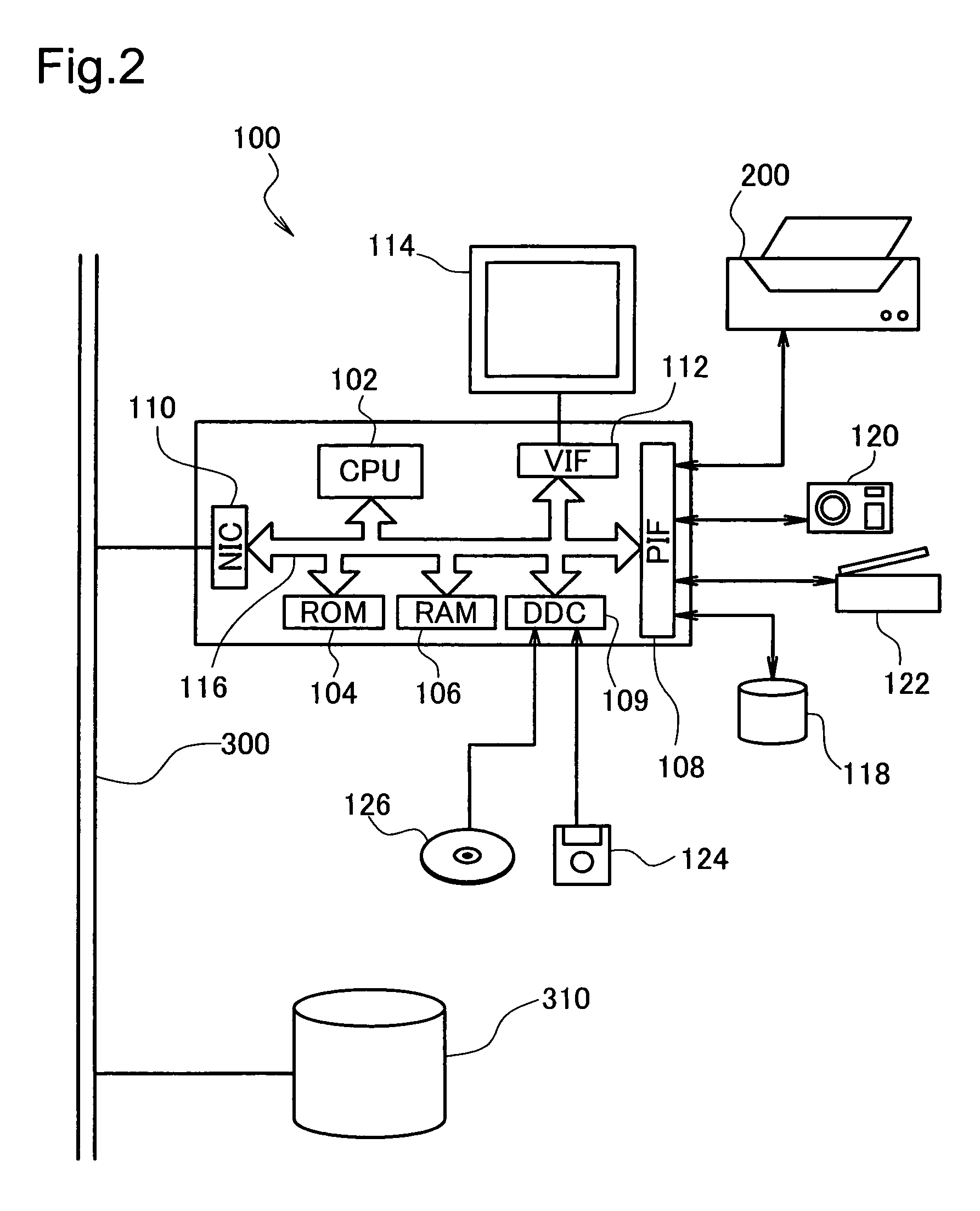
B. Device Constitution:

C. Summary of the Image Printing Process:

D. Principle of Suppressing Degradation of Image Quality Due to Dot Position misalignment:

E. Dither Matrix Generating Method:

F. Variation Examples:

A. Summary of the Embodiments:

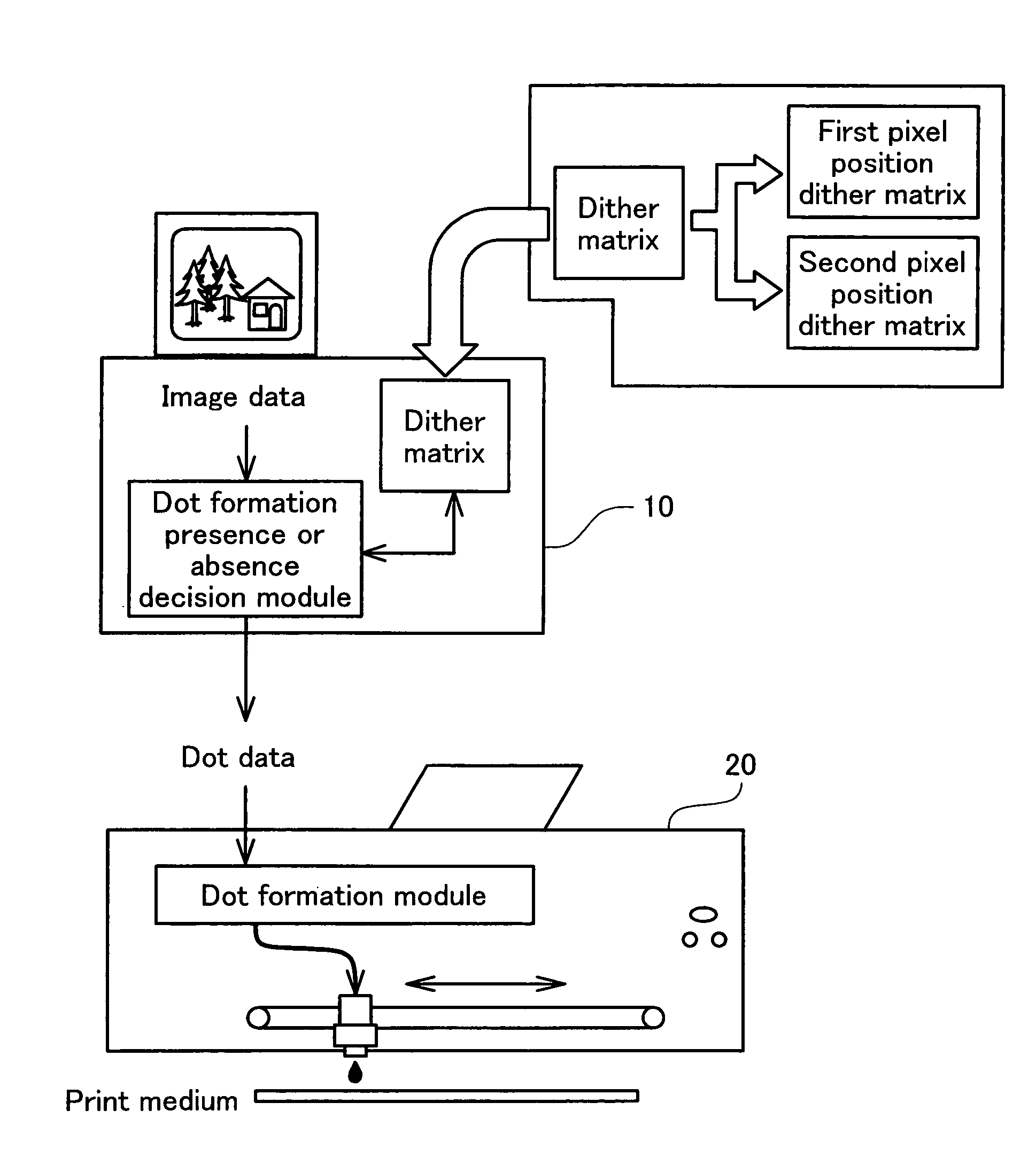
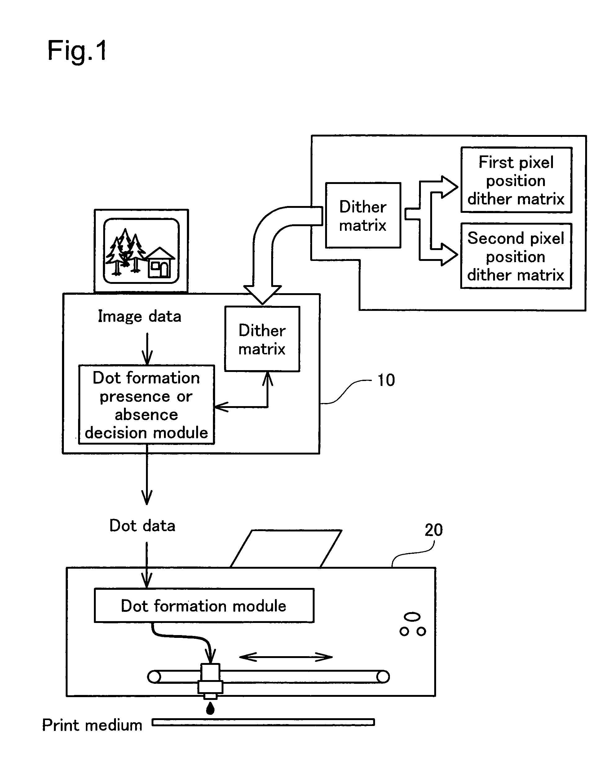
[0036]Before starting the detailed description of the embodiment, a summary of the embodiment is described while referring to FIG. 1. FIG. 1 is an explanatory drawing showing a summary of a printing system as the printing apparatus of this embodiment. As shown in the drawing, the printing system consists of a computer 10 as the image processing device, a printer 20 that prints the actual images under the control of the computer 10 and the like, and entire system is unified as one and functions as a printing apparatus.

[0037]A dot formation presence or absence decision module and a dither matrix are provided in the computer 10, and w...


PUM


Abstract

This invention provides a method for generating a dither matrix includes: setting an evaluation function for calculating an evaluation value of the dither matrix; providing a dither matrix as an initial state which stores in respective elements each of a plurality of threshold values for deciding presence or absence of dot formation for each pixel according to an input tone value; fixing an element for storing a threshold value in an increasing order from a smaller threshold value while transposing at least one of the plurality of threshold values stored in a part of the elements and a threshold value stored in another part of the elements; and outputting a dither matrix in which elements for storing are fixed with regard to at least part of the plurality of threshold values. The step of fixing an element for storing a threshold value includes: transposing mutually part of the threshold values whose elements for storing have not been fixed, among the plurality of threshold values; calculating an evaluation value of the dither matrix in which the threshold values have been transposed, using the evaluation function; fixing an element for storing a smallest evaluation threshold value among the threshold values whose elements for storing have not been fixed, according to a compliance of the evaluation value to a predetermined criterion; and repeating the steps from the transposing step to the fixing step until elements for storing at least part of the plurality of threshold values are fixed.

Description

BACKGROUND[0001]1. Technical Field[0002]This invention relates to a technology for printing an image by forming dots on a print medium.[0003]2. Related Art[0004]As an output device for images created by a computer, images shot using a digital camera, or the like, printing apparatuses that print images by forming dots on a print medium are widely used. Such a printing apparatus has tone values of dots which can be formed fewer than input tone values, and therefore expresses tone through halftone processing. The organizational dither method using a dither matrix is widely used as one of such halftone processing. The organizational dither method may have much effect on the image quality depending on the contents of the dither matrix, and therefore the dither matrix has been optimized by an analytical approach such as simulated annealing or genetic algorism using an evaluation function considering human vision as disclosed in JP-A-7-177351, JP-A-7-81190, and JP-A-1-329381, for example.[...

Claims


Application Information

Patent Timeline
Patent Type & Authority Patents(United States)
IPC IPC(8): H04N1/405
CPCH04N1/4015H04N1/4053
Inventor YAMAZAKI, SATOSHIKAKUTANI, TOSHIAKI
Owner SEIKO EPSON CORP
Features
  • R&D
  • Intellectual Property
  • Life Sciences
  • Materials
  • Tech Scout
  • Unparalleled Data Quality
  • Higher Quality Content
  • 60% Fewer Hallucinations
Learn More