Antenna device and mobile terminal apparatus equipped with the antenna device

a mobile terminal and antenna technology, applied in the direction of elongated active element feed, resonant antenna, radiating element structure, etc., can solve the problem that the bandwidth of the loop antenna corresponding to the 800 mhz band is difficult to be greatly widen, and achieve the effect of widening the frequency band

Active Publication Date: 2010-07-13
SONY CORP
View PDF14 Cites 24 Cited by
  • Summary
  • Abstract
  • Description
  • Claims
  • Application Information

AI Technical Summary

Benefits of technology

[0008]The present invention has been made in view of the above-mentioned problem, and the present invention is to provide an antenna device which makes it possible to realize a loop antenna having a greatly widened bandwidth and a multiband construction, as well as a mobile terminal apparatus equipped with such an antenna device.
[0011]According to the embodiment of the present invention, the stub antenna which corresponds to the second frequency band overlapping with the partial frequency band of the first frequency band to which the loop antenna corresponds is added to the loop antenna, so that the frequency band to which the stub antenna corresponds can be set to a frequency band in which the frequency band to which the loop antenna itself corresponds is combined with the frequency band to which the stub antenna corresponds. Accordingly, it is possible to widen the frequency band to which the loop antenna corresponds.

Problems solved by technology

As a result, there is the problem that the loop antenna corresponding to the 800 MHz band is difficult to greatly widen in bandwidth.

Method used


Image

  • Antenna device and mobile terminal apparatus equipped with the antenna device
  • Antenna device and mobile terminal apparatus equipped with the antenna device
  • Antenna device and mobile terminal apparatus equipped with the antenna device

Examples


Embodiment Construction

[0021]The present invention can be applied to mobile phones.

[General Construction of Mobile Phone]

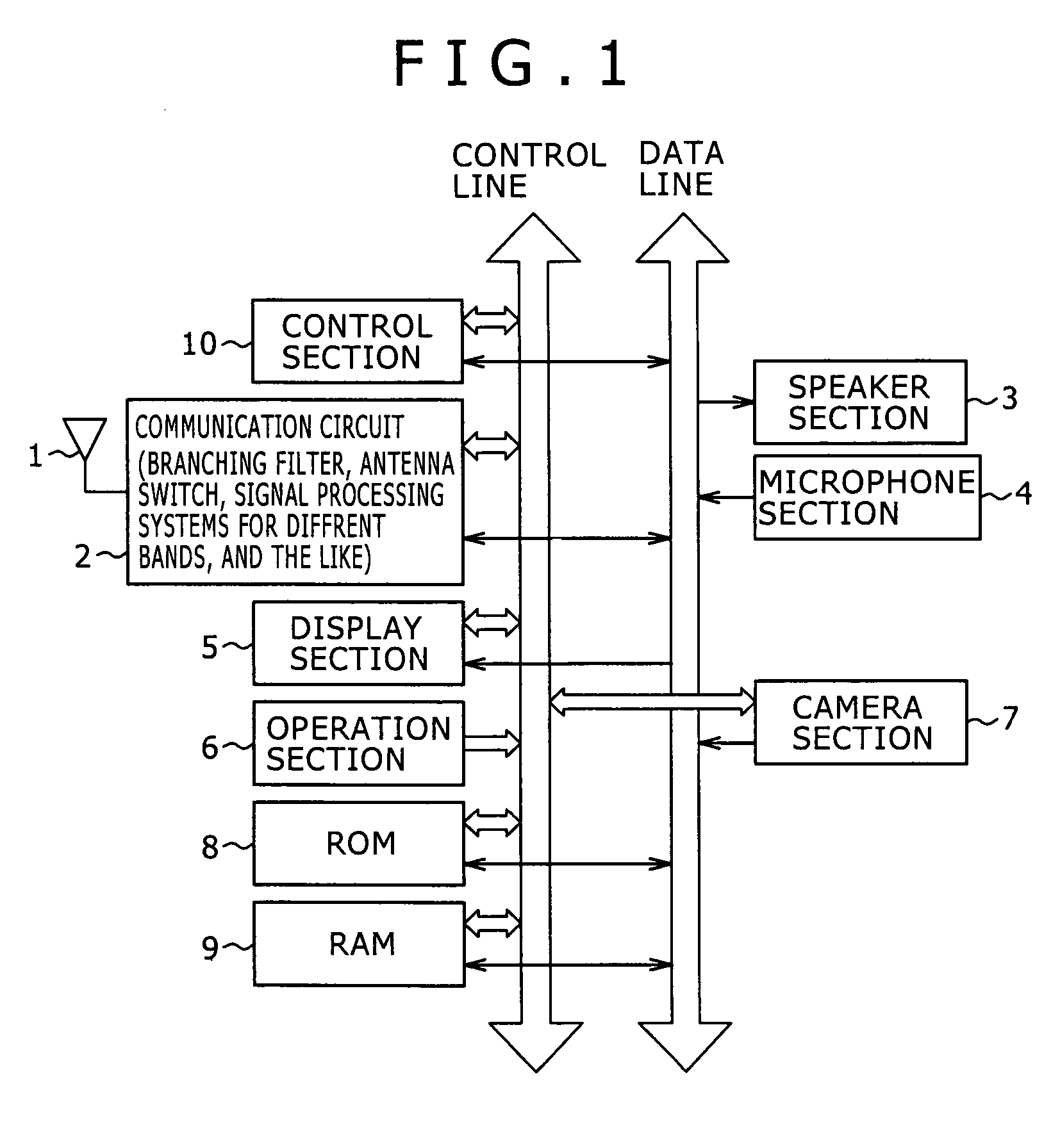
[0022]FIG. 1 shows a block diagram of a mobile phone according to an embodiment of the present invention. As shown in FIG. 1, the mobile phone according to the embodiment includes an antenna 1, a communication circuit 2, a speaker section 3, a microphone section 4 and a display section 5. The antenna 1 and the communication circuit 2 perform transmission and reception of data to and from a base station which is connected to a communications network of a mobile phone carrier. The speaker section 3 provides an audio output such as a ringtone, a received voice, the sound of a video file, or the sound of music data. The microphone section 4 collects a voice or the like to be transmitted. The display section 5 displays outgoing and incoming call numbers, the names of users who are sources and destinations, a log of incoming and outgoing calls and mobile mails, a telephone directory, an addre...


PUM


Abstract

There is provided an antenna device which includes: a loop antenna connected at one end to a feed point and connected at the other end to ground, and provided to correspond to a first frequency band; and at least one stub antenna provided in the form of extending a part of the loop antenna and provided to correspond to a second frequency band overlapping with a partial frequency band of the first frequency band to which the loop antenna corresponds.

Description

CROSS REFERENCES TO RELATED APPLICATIONS[0001]The present document contains subject matter related to Japanese Patent Application JP 2005-013005 filed in the Japanese Patent Office on Jan. 20, 2005, the entire contents of which being incorporated herein by reference.BACKGROUND OF THE INVENTION[0002]1. Field of the Invention[0003]The present invention relates to an antenna device suitable for application to mobile terminal equipment such as mobile phones, PHS phones (PHS: Personal Handyphone System) and PDA equipment (PDA: Personal Digital Assistant) having communication functions, and relates to a mobile terminal apparatus equipped with such an antenna device. More particularly, the present invention relates to an antenna device having a widened frequency bandwidth and a multi-band construction, and to a mobile terminal apparatus equipped with such an antenna device.[0004]2. Description of Related Art[0005]Japanese Patent Application Publication (KOKAI) No. 2002-43826 (pages 3 to 4:...

Claims


Application Information

Patent Timeline
Patent Type & Authority Patents(United States)
IPC IPC(8): H01Q1/24H01Q1/38H01Q5/10H01Q5/371H01Q7/00
CPCH01Q1/243H01Q1/38H01Q5/371H01Q9/42H01Q7/00
Inventor ISHIMIYA, KATSUNORI
Owner SONY CORP
Why Eureka
Try Eureka