Plasma display apparatus

a technology of plasma and display apparatus, applied in the direction of instruments, static indicating devices, etc., can solve problems such as inducing an erroneous discharge, and achieve the effect of preventing an erroneous discharge and improving a residual image spo

Inactive Publication Date: 2010-07-13
LG ELECTRONICS INC
View PDF18 Cites 1 Cited by
  • Summary
  • Abstract
  • Description
  • Claims
  • Application Information

AI Technical Summary

Benefits of technology

[0009]The present invention is to provide a plasma display apparatus for limiting a difference between a lowest setdown voltage and a sustain bias voltage to a predetermined range, thereby preventing an erroneous discharge, and improving a residual image spot.

Problems solved by technology

Long time driving of the plasma display apparatus reduces a discharge initiation voltage because of impure gas or contaminant particles existing within the plasma display apparatus, or an irregular distribution of wall charges.
The reduction of the discharge initiation voltage causes a drawback of inducing an erroneous discharge such as turning on a cell to turn off, and generating a spot because of a sustain discharge even without an address discharge.
In particular, in case where an image is converted into a different image after being continuously displayed, there is a drawback of generating a residual image spot in which the spot is generated in a residual image portion.

Method used


Image

  • Plasma display apparatus
  • Plasma display apparatus
  • Plasma display apparatus

Examples


Embodiment Construction

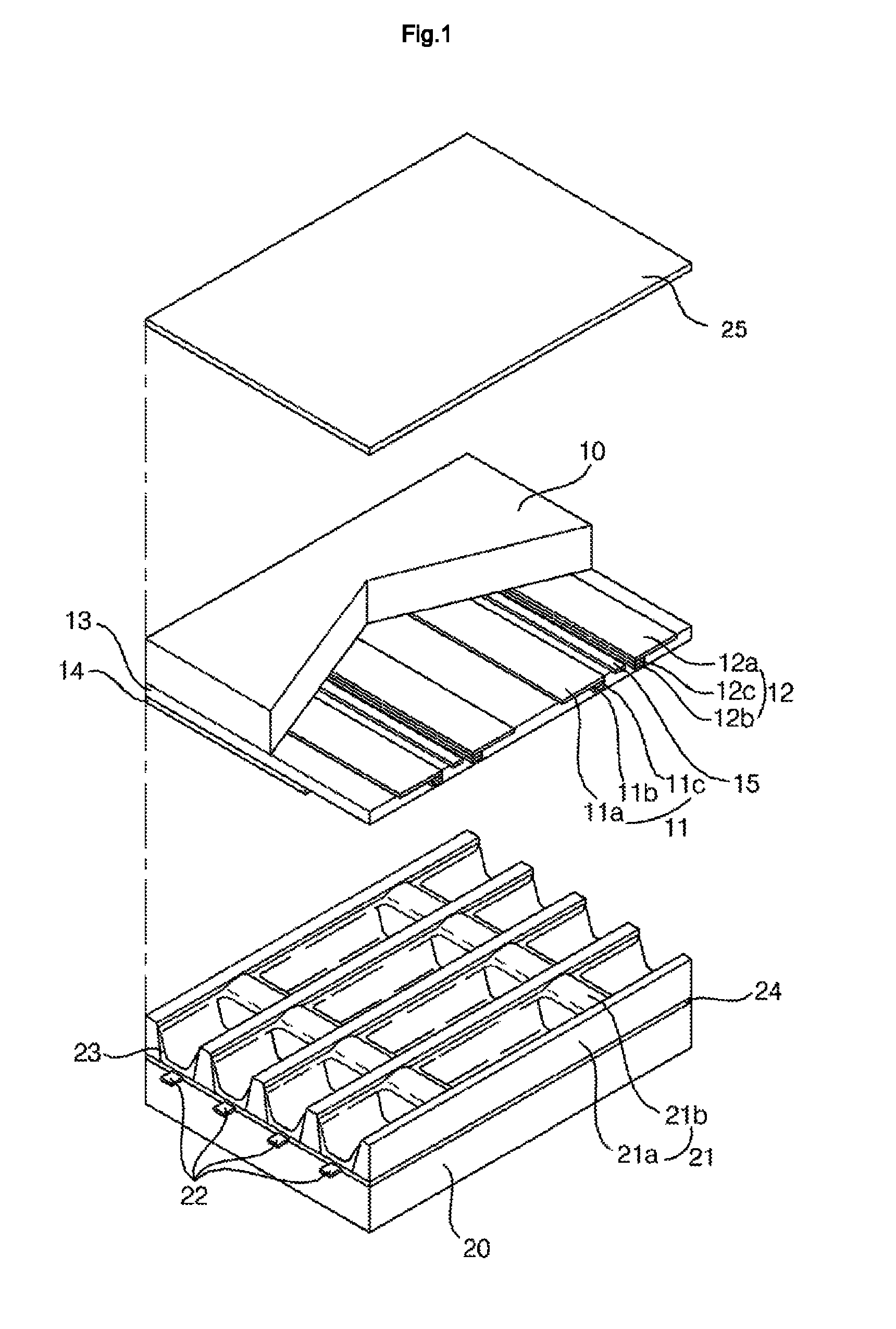
[0025]Preferred embodiments of the present invention will be described in a more detailed manner with reference to the drawings. FIG. 1 is a perspective diagram illustrating a structure of a plasma display apparatus according to an exemplary embodiment of the present invention.

[0026]As shown in FIG. 1, the plasma display apparatus includes a scan electrode 11 and a sustain electrode 12 that constitute a sustain electrode pair formed on an upper substrate 10; and an address electrode 22 formed on a lower substrate 20.

[0027]The sustain electrode pair 11 and 12 includes transparent electrodes 11a and 12a, and bus electrodes 11b and 12b. The transparent electrodes 11a and 12a are formed of Indium-Tin-Oxide (ITO). The bus electrodes 11b and 12b can be formed of metal such as silver (Ag) and chrome (Cr). Alternately, the bus electrodes 11b and 12b can be of laminate type based on chrome / copper / chrome (Cr / Cu / Cr) or chrome / aluminum / chrome (Cr / Al / Cr). The bus electrodes 11b and 12b are forme...


PUM


Abstract

Provided is a plasma display apparatus. The plasma display apparatus includes a first electrode and a second electrode formed in parallel on an upper substrate, and a third electrode formed on a lower substrate to intersect with the first electrode and the second electrode. A driving signal is applied to the first electrode, the second electrode, and the third electrode in a reset period, an address period, and a sustain period per one subfield. The reset period comprises a setdown period. A difference between a setdown lowest voltage of the driving signal applied to the first electrode and a voltage applied to the second electrode in the setdown period is 1.2 times to 1.5 times of a sustain voltage.

Description

[0001]This Nonprovisional application claims priority under 35 U.S.C. §119(a) on Patent Application No. 10-2006-0001443 filed in Korea on Jan. 5, 2006, the entire contents of which are hereby incorporated by reference.BACKGROUND OF THE INVENTION[0002]1. Field of the Invention[0003]The present invention relates to a plasma display apparatus, and more particularly, to a plasma display apparatus for limiting a difference between a lowest voltage of a setdown reset signal and a sustain bias voltage in a period for supplying the setdown reset signal, thereby preventing generation of a residual image spot.[0004]2. Description of the Background Art[0005]Plasma display panel (PDP) refers to a device for displaying an image including a character or a graphic by applying a predetermined voltage to electrodes provided in a discharge space, inducing a discharge, and exciting a phosphor using plasma generated upon gas discharge. The plasma display panel has an advantage of facilitating its large...

Claims


Application Information

Patent Timeline
Patent Type & Authority Patents(United States)
IPC IPC(8): G09G3/28G09G3/288G09G3/292G09G3/293G09G3/294G09G3/298
CPCG09G3/2022G09G3/2927G09G3/2932G09G3/2944G09G3/298G09G3/294G09G2320/0238G09G2320/0257G09G2320/041G09G2320/046G09G2320/0673G09G3/296
Inventor KIM, CHAN WOOKANG, SEOK DONG
Owner LG ELECTRONICS INC
Why Eureka
Try Eureka