
Image forming apparatus having intermediate transfer member with residual surface potential characteristic

a transfer member and potential characteristic technology, applied in the field of image forming apparatus, can solve the problems of insufficient prevention of residual image formation, inability to prevent residual image formation in next, and inability to uniformly electrify the surface of intermediate transfer member in the secondary transfer process, so as to prevent image noise

Active Publication Date: 2010-07-13
KONICA MINOLTA BUSINESS TECH INC
View PDF11 Cites 2 Cited by
  • Summary
  • Abstract
  • Description
  • Claims
  • Application Information

AI Technical Summary

Benefits of technology

"The present invention provides an image-forming apparatus that can prevent image noises caused by residual images, even when an intermediate transfer member having a surface layer is used. The invention achieves this by controlling the residual surface potential of the intermediate transfer member and the moving distance and speed of the intermediate transfer member during the secondary transfer process. This results in a high-quality image transfer and reduced image noise."

Problems solved by technology

However, electrification of the intermediate transfer member surface is not uniform in the secondary transfer process.
Thus when the intermediate transfer member surface is electrostatically charged unevenly, the electrostatic charge distribution on the surface forms a latent image, causing formation of residual images thereof (irregularity in density) in next images.
However, it is not possible to prevent the residual image sufficiently even by such a method.

Method used


Image

  • Image forming apparatus having intermediate transfer member with residual surface potential characteristic
  • Image forming apparatus having intermediate transfer member with residual surface potential characteristic
  • Image forming apparatus having intermediate transfer member with residual surface potential characteristic

Examples


examples

Preparation of Transfer Belt A

[0070]A seamless substrate having a surface resistivity of 1.30×10⁹Ω / □ and a thickness of 0.15 mm containing carbon dispersed in PPS resin was prepared by extrusion molding.

[0071]An acrylic UV-curing resin (Sanrad, manufactured by Sanyo Chemical Industries, Ltd.) containing zinc antimonate dispersed therein at an amount of 3.0 wt % with respect to the total amount was applied on the external surface of the substrate and cured by UV irradiation to form a resin layer having a thickness of 3 μm, to give a transfer belt A.

[0072](Preparation of Transfer Belts B to J)

[0073]Transfer belts B to J were prepared in a manner similar to the transfer belt A, except that the zinc antimonate content and the thickness of the cured resin layer were adjusted so that the surface resistivity and the volume resistivity may be those shown in Table 1.

[0074](Evaluation)

[0075]

[0076]The residual potential on the transfer belt surface after L / S seconds was determined by the metho...


PUM


Abstract

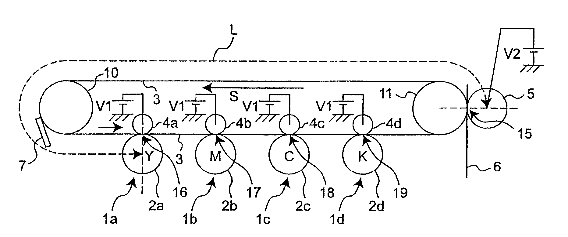
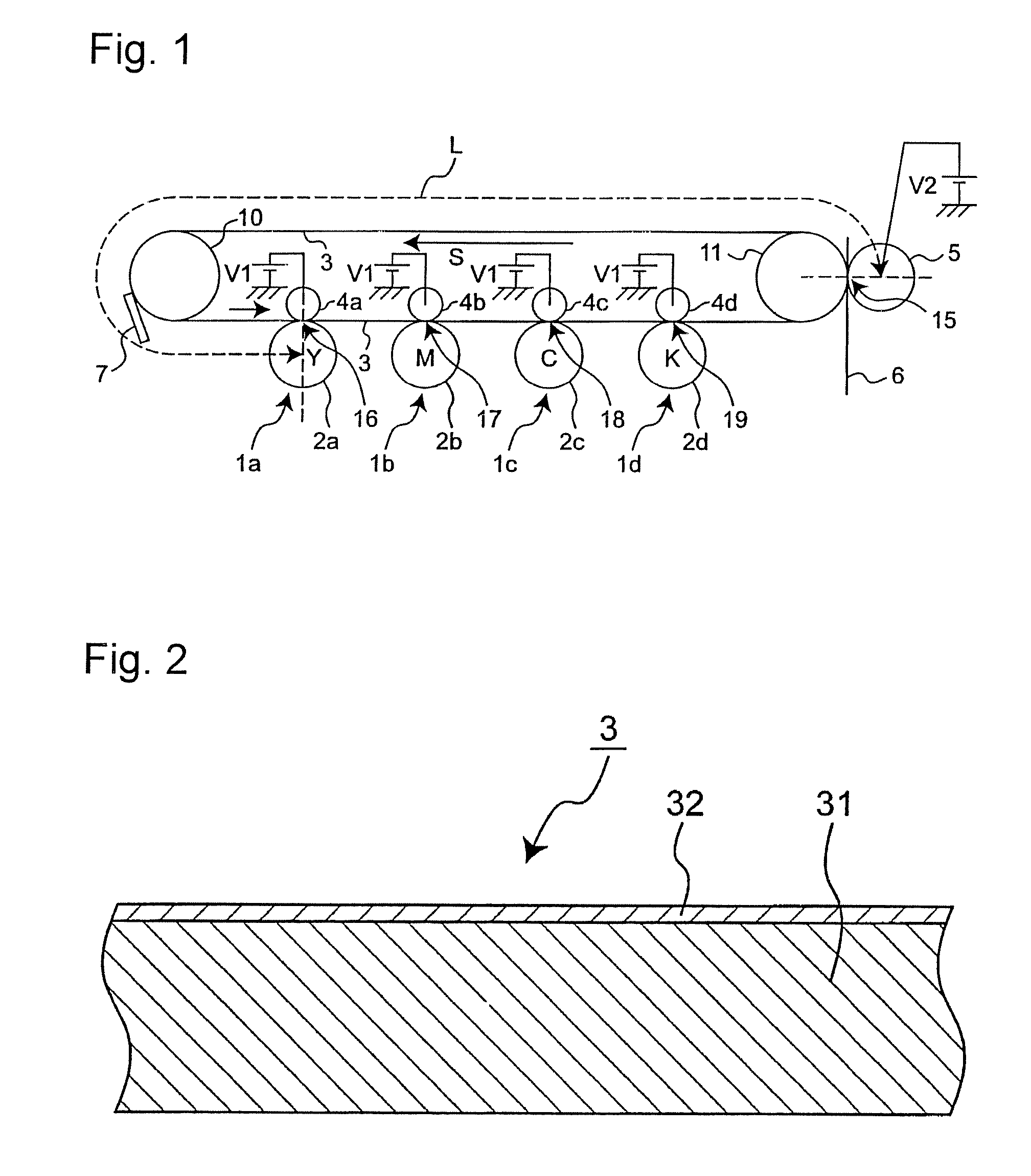
An image-forming apparatus, equipped with an intermediate transfer member 3 having a surface layer that holds a toner image primary-transferred from a latent image-supporting member temporarily on the surface layer and allows secondary transfer of the toner image held thereon to an image receiving medium,wherein, when the moving distance of the intermediate transfer member surface from the secondary transfer region 15 to the first primary-transfer region 16 is designated as L (mm) and the moving speed of the intermediate transfer member as S (mm / second), the residual surface potential of the intermediate transfer member L / S seconds after application of the secondary transfer voltage is 1 / 20 or less of the first primary transfer voltage V1.

Description

[0001]This application is based on application(s) No. 2007-114118 filed in Japan, the contents of which are hereby incorporated by reference.BACKGROUND OF THE INVENTION[0002]1. Field of the Invention[0003]The present invention relates to an image-forming apparatus for use in monochromic / full-color copying machines, printers, fax machines, multifunctional processing machines thereof etc.[0004]2. Description of the Related Art[0005]In a full-color image-forming apparatus in the intermediate transfer process, a color image is formed, for example, by once transferring toner images different in color that are developed on multiple photosensitive members onto an intermediate transfer member to be superimposed and transferring the superposed toner images all together onto an image receiving medium such as paper. The transferring process from photosensitive member to intermediate transfer member is called primary transfer, while that from intermediate transfer member to image receiving medi...

Claims


Application Information

Patent Timeline
Patent Type & Authority Patents(United States)
IPC IPC(8): G03G15/01
CPCG03G15/1605G03G2215/0132G03G2215/1614G03G15/162
Inventor MORI, TOMOHIDEINADA, YASUYUKIHIROI, TOSHIAKI
Owner KONICA MINOLTA BUSINESS TECH INC
Learn More